Operation of TOPODRONE LiDAR without GNSS signal is not possible.
##### TOPODRONE LiDAR 100 / 100+ / 200+ is based on the following modules and systems: 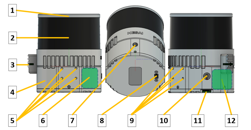 1. LiDAR sensor housing; 2. Sensor lens; 3. Operation status LED; 4. TOPODRONE LiDAR housing; 5. Mounting holes with M3 thread; 6. High precision inertial measurement unit (IMU); 7. LEMO FFA.00 connector for external GNSS antenna cable connection; 8. USB Type-C 2.0 connector; 9. Mounting holes with M3 thread; 10. LEMO 6 pin connector; 11. Micro-SD memory card slot; 12. GNSS receiver TOPODRONE. ##### Description of TOPODRONE LiDAR 100 / 100+ / 200+ components: 1\. LiDAR Hesai sensor housing. Made of aluminium alloy, coated with grey enamel. During operation, the housing may slightly vibrate and make sounds and may heat up to 60°C. This effect is caused by the rotation of the scanning units of the laser heads inside the case, as well as heat dissipation from the working internal components. 2\. LiDAR Hesai sensor lens. It is made of glass with polymer anti-reflective coating. It acts as a filter that transmits light only in the working wavelengths of the laser, as well as mechanical protection of the scanning rotating laser heads of the sensor. The coating of the laser scanning sensor lens is vulnerable to scratching and chipping. It is strongly recommended that the TOPODRONE LiDAR lens be treated with care and not be operated under conditions that could damage or scratch the surface of the laser scanning sensor. If scratches and damage occur, the quality of the acquired data may deteriorate. Individual single minor scratches do not generally reduce the quality of the data. 3\. TOPODRONE LiDAR status LED. Displays the current operating status of the device. Below is the decoding of the light signals:| **Switching on and off** | ||
| 1 | Infrequent **green **flashes | Charging Ionistors Normal ~10 seconds |
| 2 | Flashing **green** | Linux booting Normal ~20 seconds |
| 3 | Flashing **red**, siren | After 1 minute of flashing green Linux failed to boot Problem with image or flash drive |
| 4 | **Green** | Linux booted, waiting for services Normal ~10 seconds |
| 5 | Rapid flashing **green** | After power off, shutdown. Normal ~10 seconds |
| **Waiting for and recording data** | ||
| 6 | **Green** | System initialisation |
| 7 | Siren, flashing **red** | Hardware problem with Ublox or IMU |
| 8 | **Green **flashing **orange** | Waiting for GNSS signal The better the signal, the faster the flicker |
| 9 | **Green** | Time setting Normally ~ 1 c |
| 10 | **Green** flashing **blue** | Start recording Normally ~ 10 s |
| 11 | Triple signal, **blue** | Recording |
| **Copying data (after connecting a USB stick)** | ||
| 12 | **Green** | Recording stopped Normal ~ 1 c |
| 13 | Flashing **crimson**, rising tone signal | Start copying |
| 14 | One flash **red**, siren | Error mounting the USB stick Faulty USB stick or file system |
| 15 | Two flashes **red**, siren | Not enough space on the USB stick |
| 16 | Flashing **crimson** | Copying data Flickering speeds up during copying process |
| 17 | Fast flashing red, siren | Write error |
| 18 | Green, decreasing tone signal | All data copied |