TOPODRONE P61 Multispectral camera
- Disclaimer
- Product features
- Turning on and initializing TOPODRONE P61 and GNSS receiver
- Сustomization the camera profile for route building
- Using the TOPODRONE P61 with a lens for shooting in the visible range
- TOPODRONE P61 output to the Internet for diagnostics
- Adjusting the image settings
- Memory card: recommendations, installation, data uploading
- Requirements and operating conditions
- Multispectral data processing TOPODRONE P61
Disclaimer
The TOPODRONE P61 with multispectral AGROWING lenses is a photogrammetric camera designed to capture terrain objects. Processing of the received materials can be performed in any photogrammetric software. TOPODRONE UAV PPK UPGRADE KIT geodetic receiver, working together with the camera, allows you to get high-precision coordinates of photocenters, synchronizing both devices by cable. The GNSS receiver records “raw” measurements in *.UBX format and shutter timestamps.
DO NOT store the TOPODRONE P61 photogrammetric camera in direct sunlight, in poorly ventilated areas, or near a heat source.
DO NOT turn the unit on or off for short periods of time. Wait at least 30 seconds before turning the unit on or off.
DO NOT use TOPODRONE P61 in humid and dusty environment, it has no IPXX protection, so using the equipment may result in malfunction. When the TOPODRONE P61 camera is not in use, store it in the protective case in which it is shipped. It is recommended to store the equipment in conditions of relative humidity not exceeding 40% and temperature 20±5°C.
DO NOT insert or remove the memory card while the camera is in use.
DO NOT touch the lens surface with your hands or any sharp objects, otherwise you may scratch the surface of the lens, which will affect the quality of the images.
DO NOT detach the lens while the camera is in use.
Product features
The TOPODRONE P61 photogrammetric camera is equipped with a full-frame CMOS sensor with a global mechanical shutter and supports the replacement of standard lenses for visible spectrum imaging with lenses for multispectral imaging. This camera can be mounted on a 3-axis suspension or together with one of the TOPODRONE laser scanners.
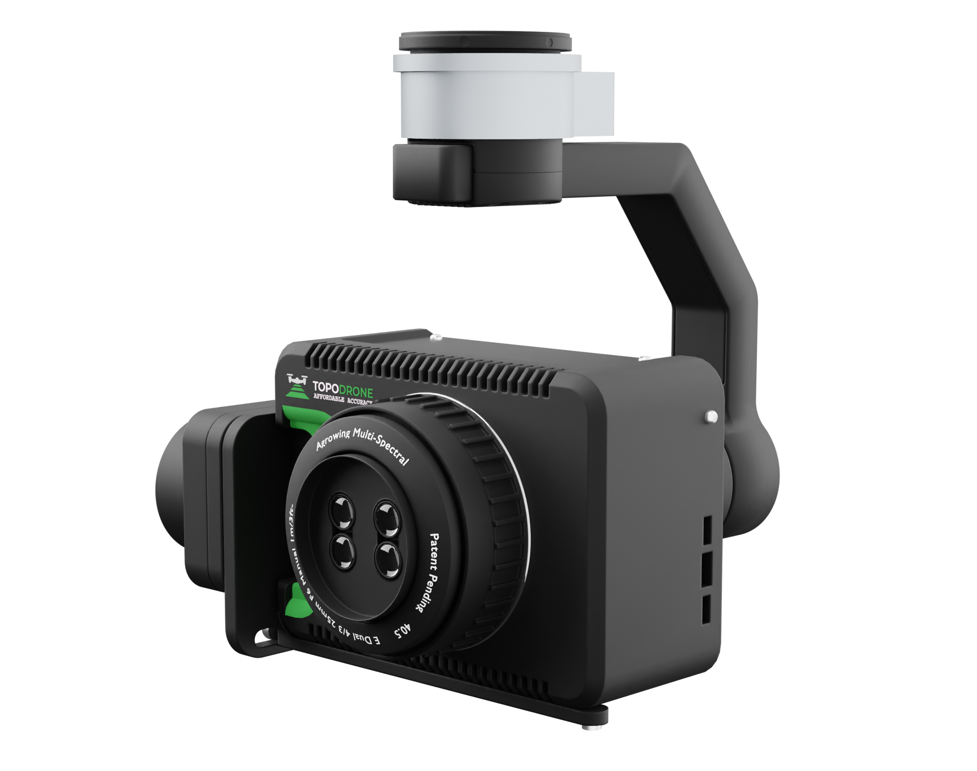
Photogrammetric camera TOPODRONE P61 with AGROWING QUAD lens mounted on 3-axis suspension.
Supply package
- Photogrammetric camera TOPODRONE P61
- Lens for TOPODRONE P61*
- 3-axis suspension*
- GNSS receiver TOPODRONE UAV PPK UPGRADE Kit with MicroSD card 16 GB*
- Power and shutter connection cable LEMO 4 PIN / LEMO 6 PIN*
- USB to LEMO 6 PIN cable for connecting the camera to the internet and diagnostics
- GNSS antenna plate with cable and mounting screws*
- External GNSS antenna*
- SD XC-I 64 GB memory card*
- Protective case for transportation*
- L-shaped platform with screws for attaching the camera to the laser scanner*
- Skyport-SHLD adapter*
- AGROWING Quad/Sextuple Lens
- UV/IR Magnetic Clip-In Filter for Sony E-Mount
- Cleaning Tools
* - depends on the delivery package.
TOPODRONE photogrammetric camera device
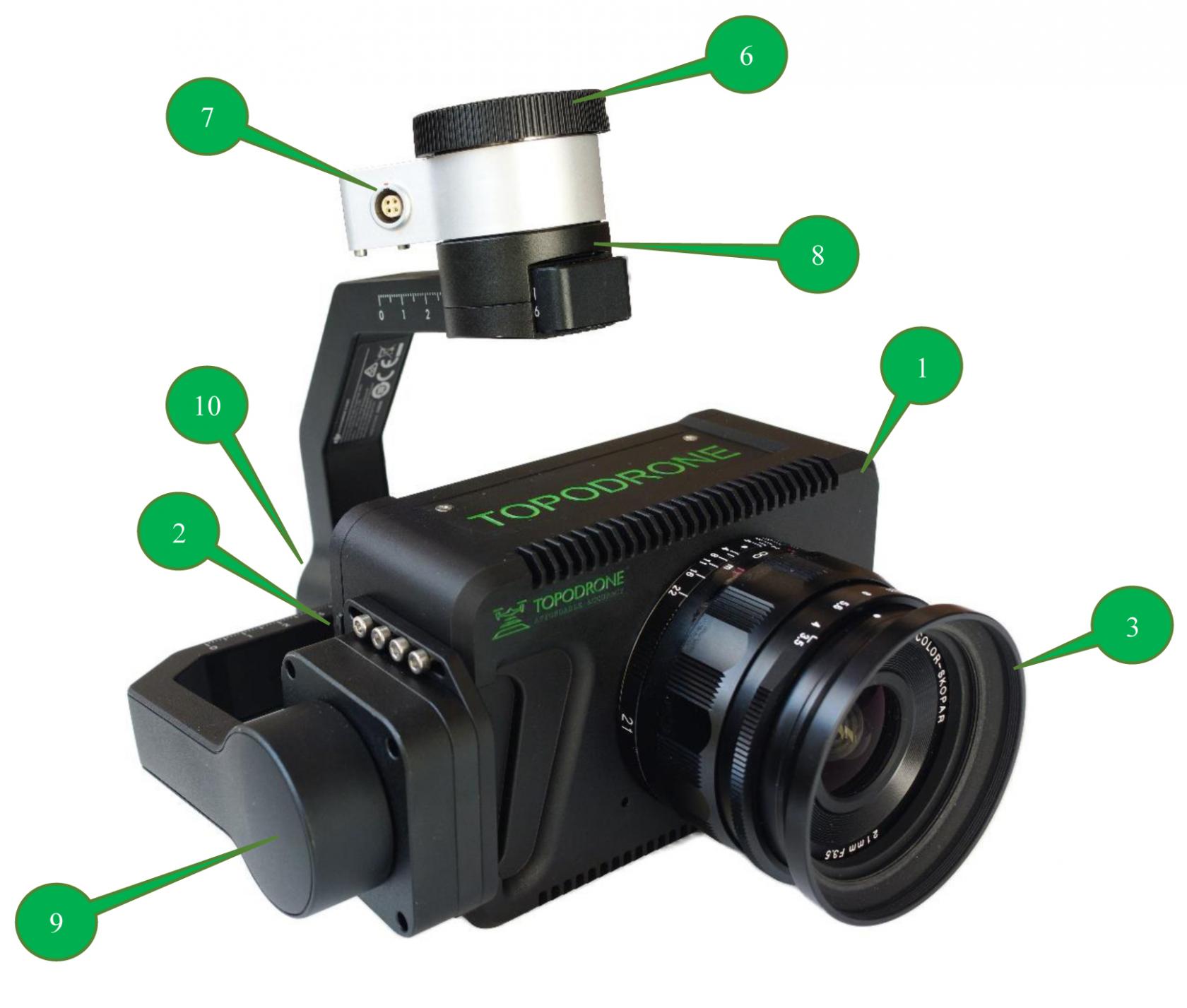
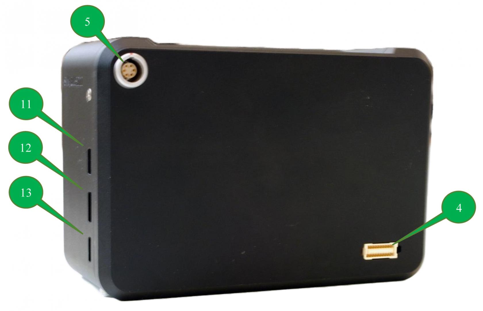
- Main body
- SD memory card
- Lens
- SHLD connector for connecting a camera with a 3-axis suspension or connecting to a drone through a Skyport-SHLD adapter.
- LEMO 6 pin connector for camera maintenance and connection to the TOPODRONE laser scanner when used together.
- Connector for 3-axis stabilizer X-Port
- Connector for connection to the TOPODRONE UAV PPK Upgrade Kit or to the TOPODRONE laser scanner.
- Camera rotation motor
- Tilt axis motor
- Roll axis motor
- Micro HDMI - for connecting camera to monitor
- USB type-C connector
- Multi/Micro USB.
Supported drone
The TOPODRONE P61 photogrammetric camera can be used on almost any drone, it is recommended to consult the manufacturer of the equipment.
Full control and transmission of the video stream in real time to the remote control is possible only on DJI Matrice 2** and 3** series drones.
Compatible lenses
TOPODRONE P61 supports lenses with Sony E mount. The camera can be supplied with one of the following lenses: Sony FE 24mm f/2.8 G or Voigtlander Color-Skopar 21mm f/3.5. Specifications are shown in the table below.
|
Characteristic |
Sony FE 24mm f/2.8 G |
Sigma AF 24mm F/3.5 DG DN |
Voigtlander Color-Skopar 21mm f/3.5 |
|
Bayonet |
Sony E |
Sony E |
Sony E |
|
Focal length, mm |
24 |
24 |
21 |
|
Angle of view (APS-C), ° |
73.3 |
73.3 |
80.7 |
|
Minimum aperture value |
2.8 |
3.5 |
3.5 |
|
Maximum aperture value |
22 |
22 |
22 |
|
Minimum focusing distance, m |
0.24 |
0.11 |
0.20 |
|
Size (diameter × length), mm |
68 × 45 |
64 x 48.8 |
62,8 × 39,9 |
|
Weight, g |
162 |
230 |
230 |
TOPODRONE P24 Specification
|
Camera Type |
Mirrorless with interchangeable lens |
|
Bayonet |
Sony E |
|
Image stabilization |
Disabled |
|
Number of megapixels |
61 |
|
Sensor size |
Full frame (35.7x23.8 мм) |
|
Maximum photo size, pixel |
9504 x 6336 |
|
Sensor type |
CMOS |
|
Cropping factor |
1 |
|
Shooting Modes |
Shutter priority, Aperture priority, Manual, auto ISO |
|
ISO range |
100-32000 |
|
Shutter speed range, s |
30 – 1/8000 |
|
Supported memory card formats |
SD, SDHC (UHS-I/II compatible), SDXC (UHS-I/II compatible), microSD, microSDHC, microSDXC memory cards |
|
Maximum supported memory capacity, Gb |
512 |
|
Supported file system type |
FAT32 |
|
Built-in battery |
None |
|
Camera weight without 3-axis stabilizer, g |
685 |
|
Camera weight with 3-axis stabilizer, g |
1045 |
|
Video shooting capability |
None |
|
Operating temperature range, °C |
-20 … +40 |
|
Stabilizer tilt angle range, ° |
-130 … +140 |
|
Stabilizer rotation angle range, ° |
±320 |
TOPODRONE UAV PPK Upgrade Kit
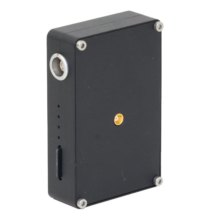
TOPODRONE UAV PPK Upgrade Kit is a small GNSS receiver with the ability to connect an external GNSS antenna and integrate with various payloads.
|
Supported GNSS systems and frequencies |
GPS: L1C/A, L2C; GLONASS: L1OF, L2OF; GALILEO: E1B/C, E5b; BEIDOU: B1I, B2I |
|
Raw measurement recording frequency, Hz |
10 |
|
Number of GNSS receiver channels, pcs. |
184 |
|
Supported memory card formats |
microSD, microSDHC, microSDXC |
|
Maximum supported memory capacity, GB |
16 |
|
Supported file system type |
FAT32 |
|
Minimum number of satellites for initialization, pcs. |
8 |
Characteristics of AGROWING lenses
| Characteristics | AGROWING Quad | AGROWING Sextuple |
| Photo |
|
|
| Matrix size, mm | 35.7x23.8 | 35.7x23.8 |
| Resolution of each multispectral image, pixel | 4300 x 2800 12 megapixels |
2700 x 2600 7.2 megapixels |
| Weight, g | 180 | 190 |
| Focal length, mm | 25 | 21.8 |
| Aperture | 6 | 5.6 |
| Field of view: Diagonal Horizontal Vertical |
46.0 |
40.8 |
| Number of channels | 10 or 9+RGB | 14 or 13+RGB |
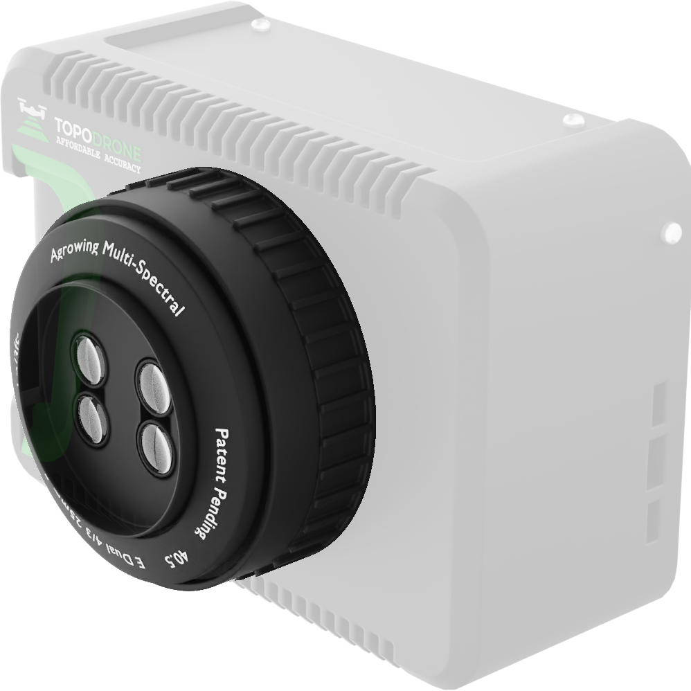
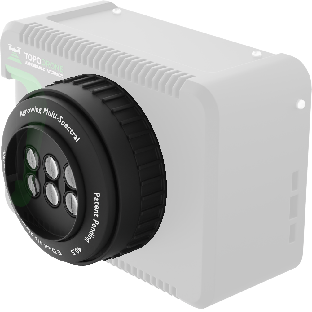
For Quad and Sextuple lenses, it is possible to replace filters from the basic configuration with filters from an additional category before purchase. This is necessary if the subjects you are shooting are better seen in a particular spectrum at a particular wavelength.
| Lens type |
Basic configuration |
Additional filters |
||||
| AGROWING Quad |
R: 850 |
R: 650 |
R: 710 |
R: 685 |
R: 710 |
R: 795 |
|
G: - |
G: 550 |
G: 570 |
G: 560 |
G: 570 |
G: - |
|
|
B: - |
B: 430 |
B: 405 |
B: 450 |
B: 480 |
B: 470 |
|
| AGROWING Sextuple |
R: 850 |
R: 650 |
R: 630 |
R: 735 |
R: 710 |
R: 795 |
|
G: - |
G: 550 |
G: 525 |
G: - |
G: 570 |
G: - |
|
|
B: - |
B: 430 |
B: - |
B: 490 |
B: 480 |
B: 470 |
|
|
|
R: 710 |
R: 685 |
|
|
|
|
|
|
G: 570 |
G: 560 |
|
|
|
|
|
|
B: 405 |
B: 450 |
|
|
|
|
Turning on and initializing TOPODRONE P61 and GNSS receiver
After successful installation of TOPODRONE P61, place the drone on a flat, hard, stable surface. High grass, sandy beaches, metal structures (such as car hoods or ship decks), slush, and puddles are unsuitable for takeoff. There is a high probability of interference with the drone's compass or affecting the initialization of the camera mount.
The takeoff location should be in an open area away from trees, buildings, power lines and other obstacles. Turn on the drone, 5-7 seconds after the power supply, the suspension with the TOPODRONE P61 camera will begin initialization, calibrating, rotating in different directions. Do not obstruct the rotation or move the drone at this moment. Wait for the suspension calibration procedure to finish, it usually takes 10-15 seconds.
Simultaneously with the suspension, the TOPODRONE GNSS receiver initializes and searches for the GPS signal when receiving power. If there is even a small GNSS signal from several satellites, TOPODRONE will start recording kinematics data on the internal Micro-SD memory card. Normal initialization time of the TOPODRONE receiver is 15-60 seconds.
Main elements of the TOPODRONE GNSS receiver

- Cable connecting the GNSS receiver module and pendant to the TOPODRONE 61 camera.
- Green colored LED. Indicates that power is being supplied to the GNSS receiver.
- Orange color LED. Indicates the status of recording to the memory card. During recording, the LED blinks rapidly. Each blink corresponds to the recording of 4 KB of data
- LED blue. Indicates the signal quality of the GNSS antenna
- Red LED Indicates that there are errors in the system. If an error occurs, check the memory card. If replacing or formatting the micro-SD card does not solve the problem, contact support.
- Micro-SD card slot.
- GNSS antenna coaxial cable.
Each time the receiver is turned on, a new .ubx file is created in the folder named DD-MM-YY (day-month-year) with the format name HH-MM-SS (hours-minutes-seconds).
| SIGNAL STATUS | DESCRIPTION |
| is off | PDOP>10 |
| flashing slowly | 3<PDOP<10 |
| flashing fast | 2<PDOP<3 |
| continuously on | PDOP<2 |
Indication of blue LED of TOPODRONE GNSS receiver
The time is recorded in UTC format. The file is created only after the GNSS receiver catches the signal from the satellites. Do not insert or remove a memory card while the receiver is operating. This operation should only be performed with the power off. The maximum allowable memory card capacity is 64 GB. The format is FAT32. The GNSS receiver records a UBX file at 10 Hz and receives GPS and GLONASS signal on L1 and L2 frequencies. After successful initialization, the following LEDs should be lit on the TOPODRONE receiver: green (constant), blue (constant), orange (flashing).
Сustomization the camera profile for route building
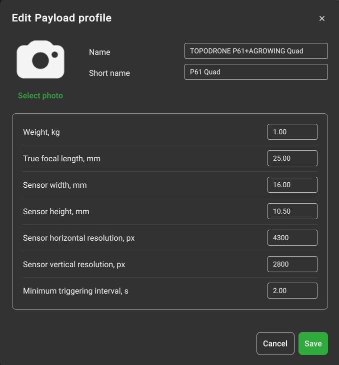
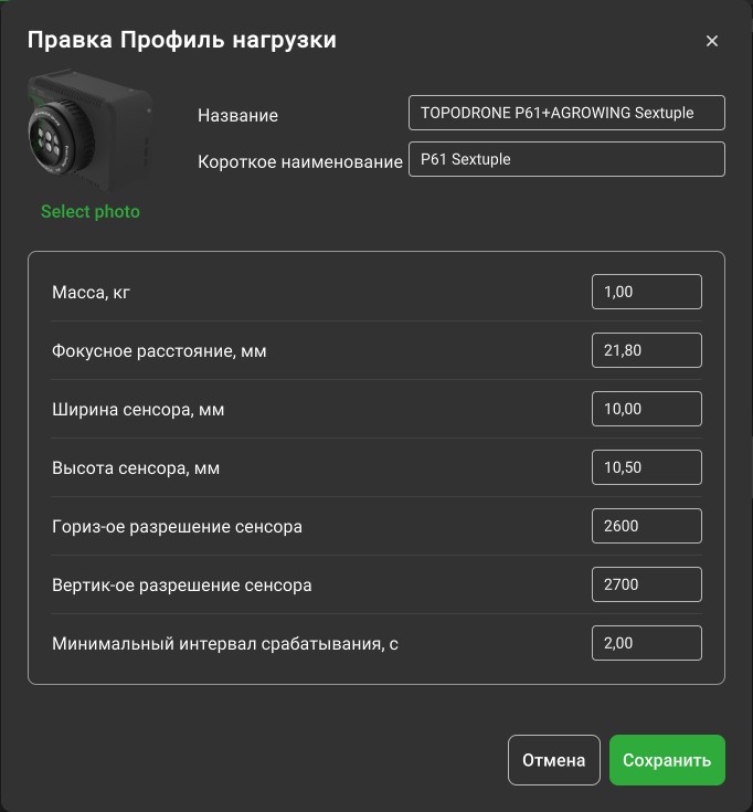
Сustomization the TOPODRONE 61 profile with the AGROWING multispectral lens in the UgCS software
UgCS is software designed to manage drones and perform various tasks in mapping, monitoring, agriculture, infrastructure inspection and other applications. UgCS offers an intuitive interface and allows you to efficiently plan and manage drone flights, as well as process the acquired data.
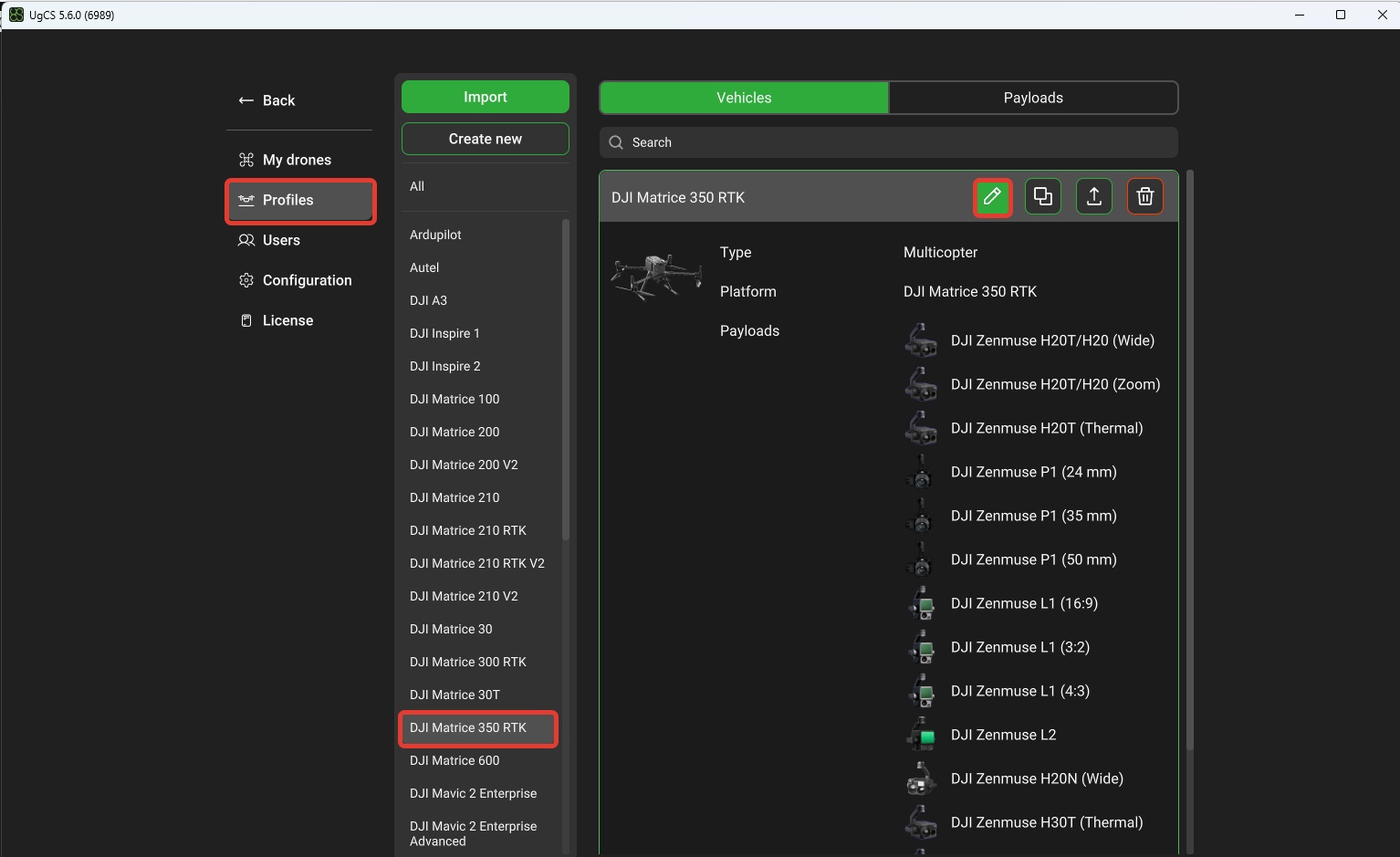
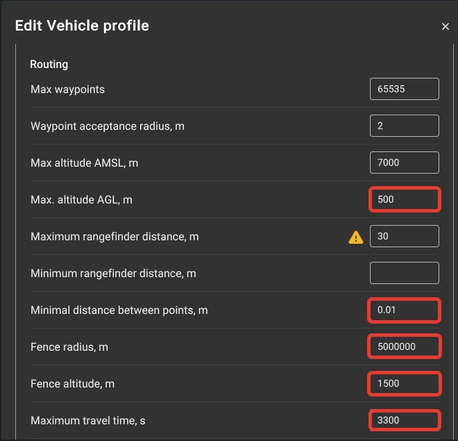
For correct flight planning in UgCS it is necessary to customize drone profile parameters and payload parameters.
Click "Menu" / "Main Menu" / "Profiles" / "Drone Model Name" / "Edit Object".

In the "Route restrictions" section, change the highlighted parameters to the values shown in the figure.
Then go to the “Loads” tab to customize the camera profile.

And import the required profile. (Profiles can be downloaded from the links below)
TOPODRONE P61+AGROWING Quad.profile
TOPODRONE P61+AGROWING Sextuple.profile
If necessary, all camera parameters can be entered manually. To do this, click create and enter the required values in the window that opens.
|
|
|
Сustomization TOPODRONE 61 profile with AGROWING multispectral lens in DJI Pilot 2 software
Turn on the Smart Controller and open DJI Pilot 2.
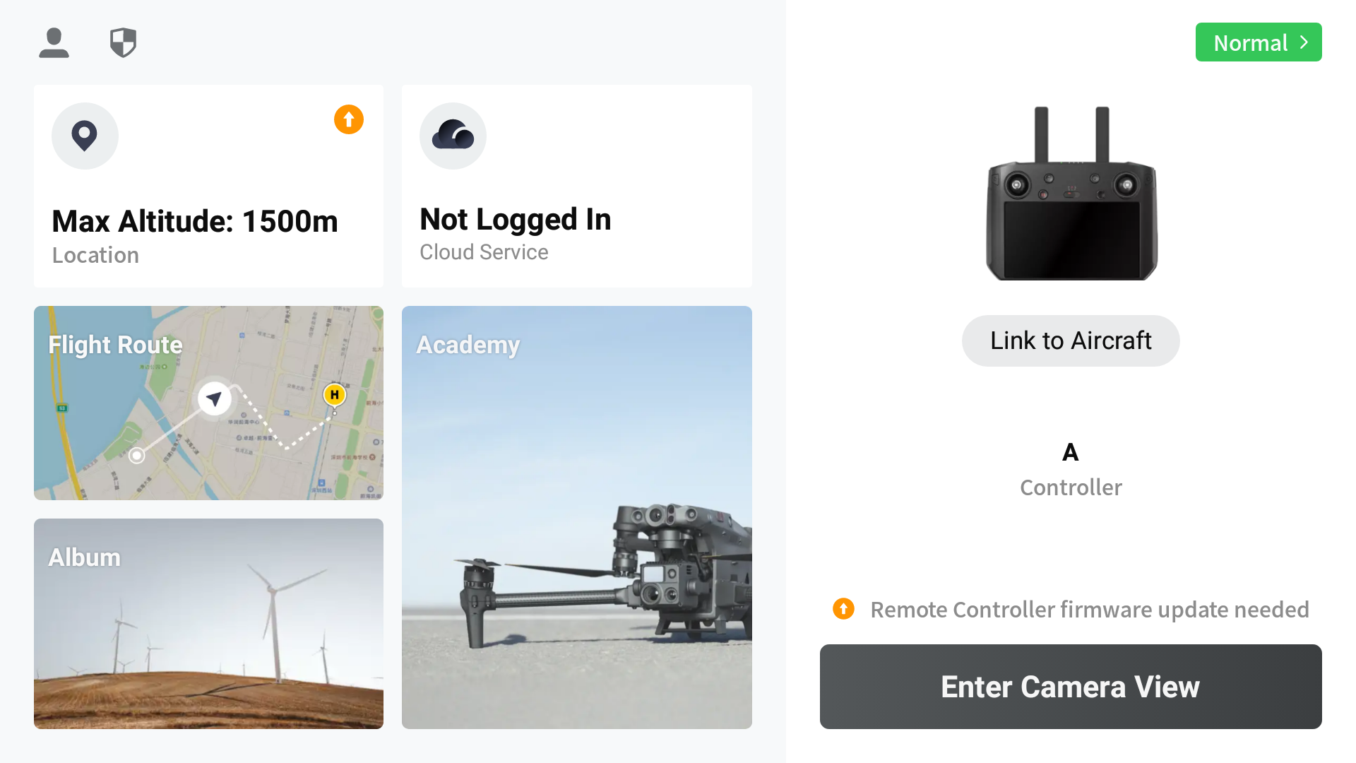
Select the Flight Route tab and create a new route for mapping.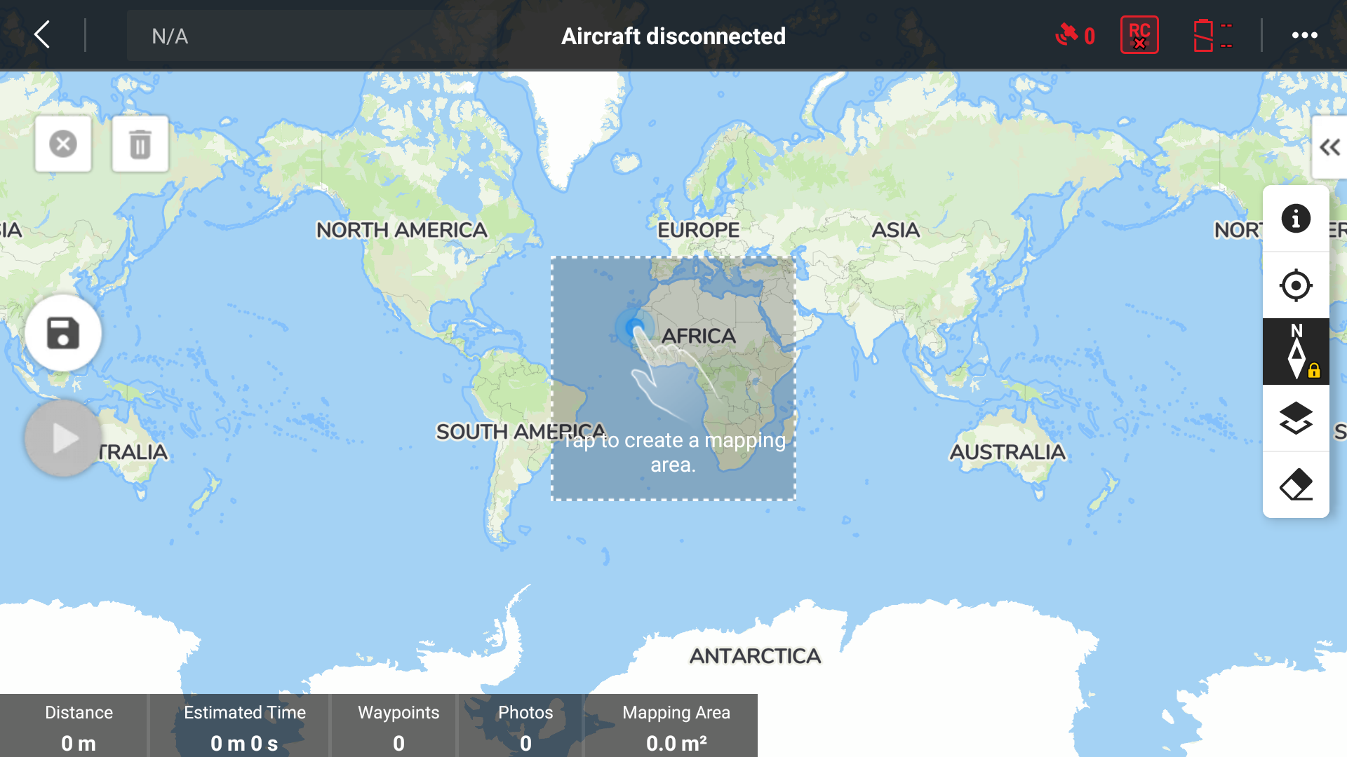
Tap to the map to created a mapping area. Next, click the "Select Camera" / "Custom camera" button and add a new camera.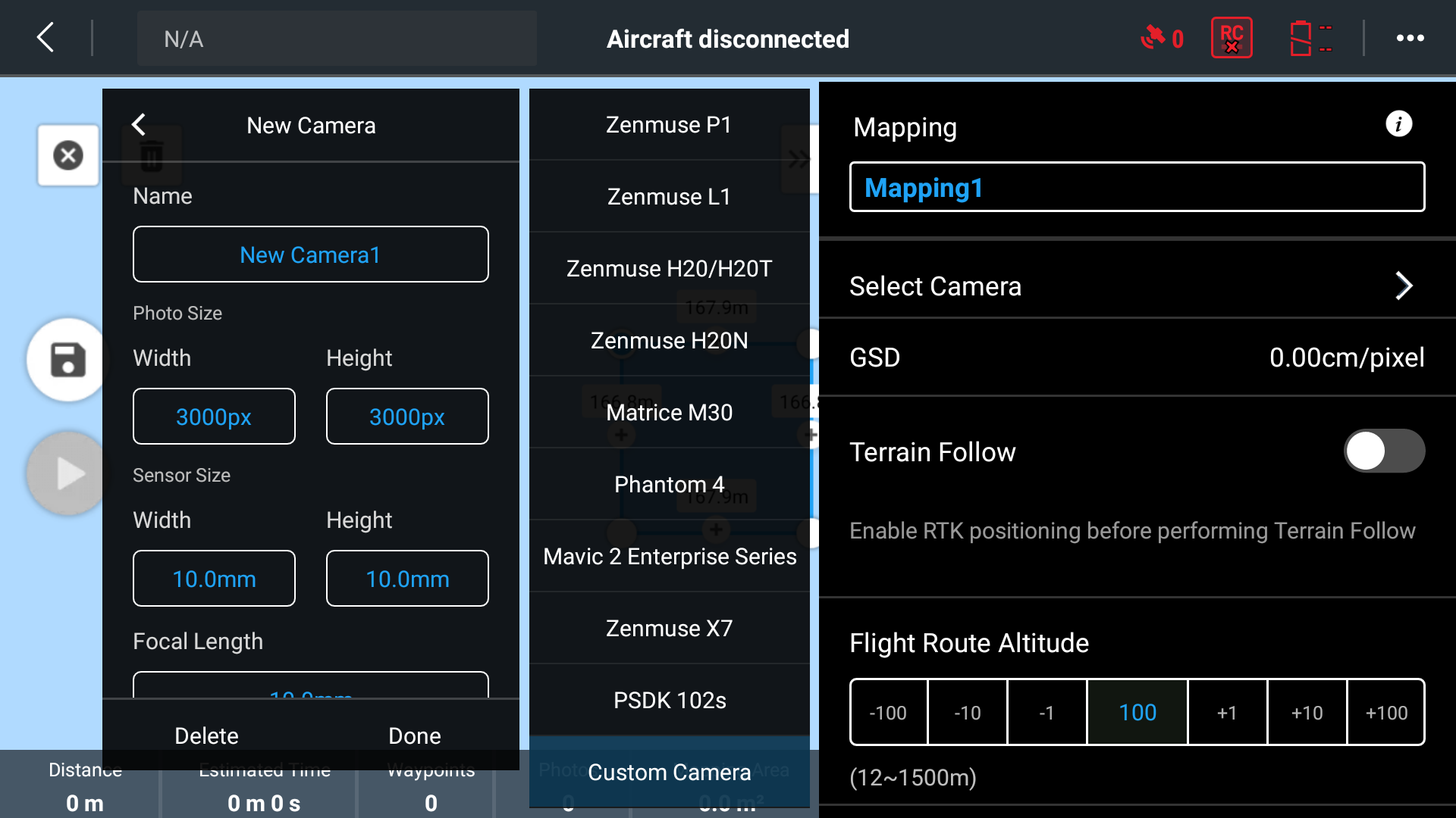
Enter the camera name, photo size, sensor size, focal length, minimum photo interval, and click the “Done” button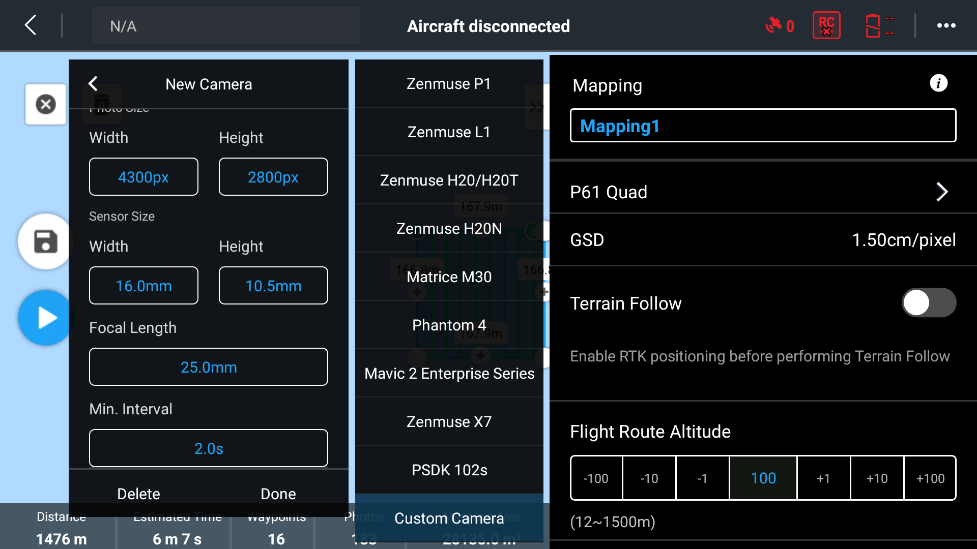
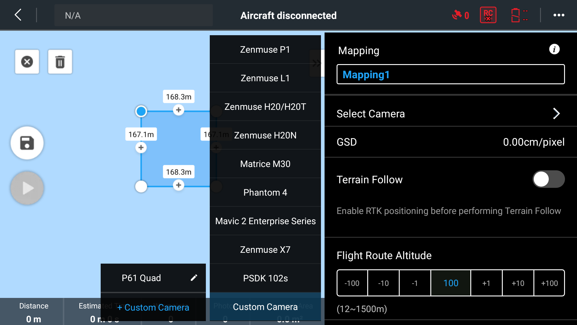
Now you can move on to mission planning.
Using the TOPODRONE P61 with a lens for shooting in the visible range
During the production of the TOPODRONE P61 multispectral camera, the matrix is modified: the ultraviolet filter is removed from it. This filter is necessary for the camera to work correctly in the visible range, and removing the filter improves the sensitivity of the matrix to other spectra forming a multispectral image.
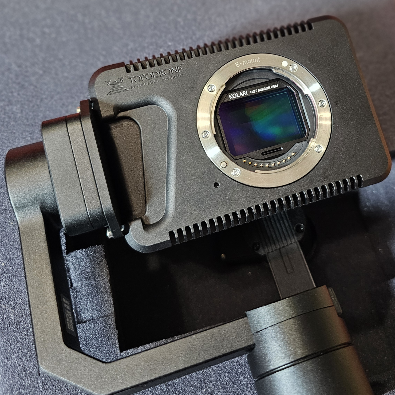
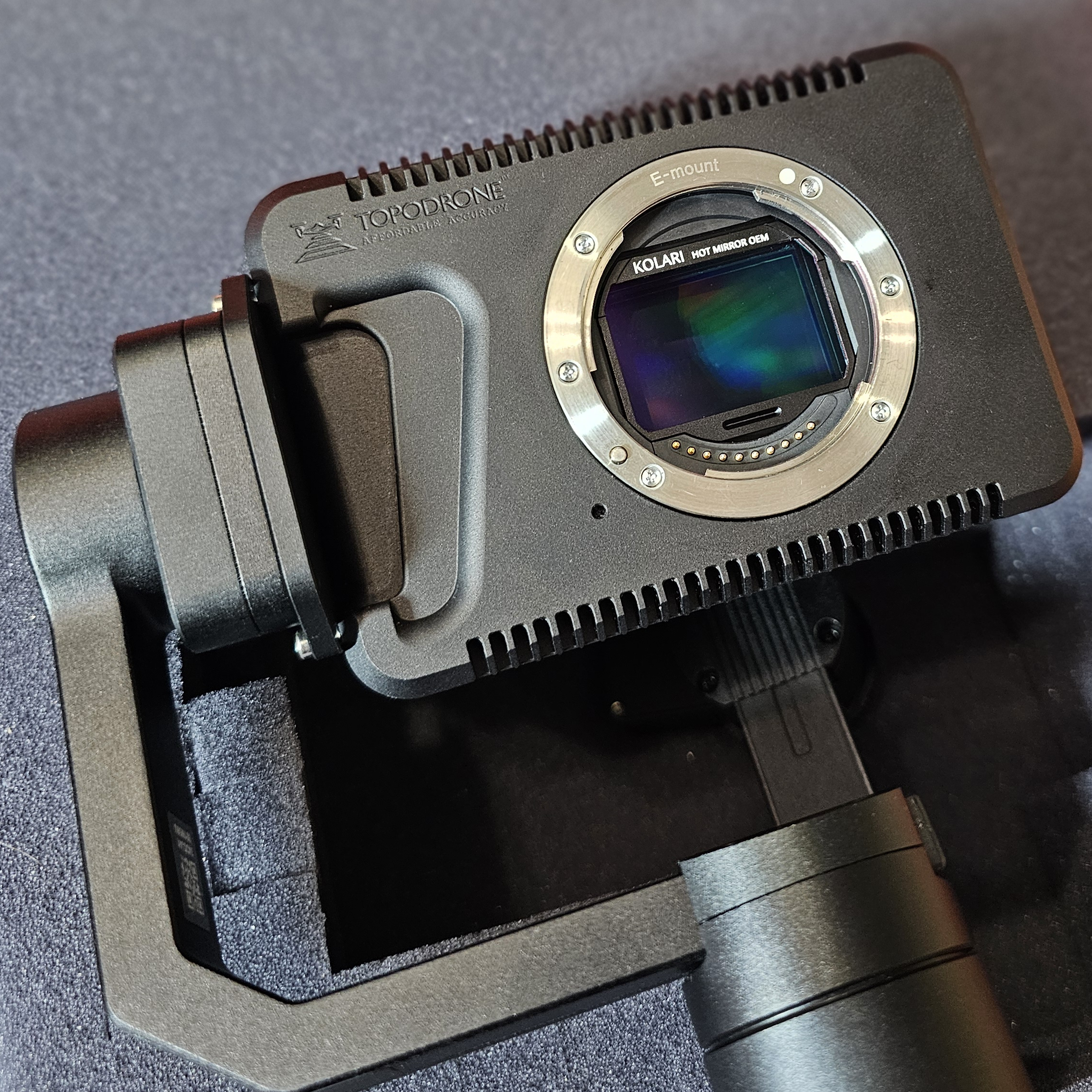
UV filter is necessary for aerial photography in the visible spectrum. This allows you to eliminate possible distortions caused by ultraviolet radiation, which can affect the color reproduction and quality of the final images. In this regard, the optimal solution is the introduction of a quick-change UV/IR Magnetic Clip-In Filter for Sony E-Mount, which is installed directly between the lens and the camera sensor. The process of installing the filter is simple, requires no special skills and takes less than one minute. To install the UV/IR Magnetic Clip-In Filter for Sony E-Mount, follow the steps below:
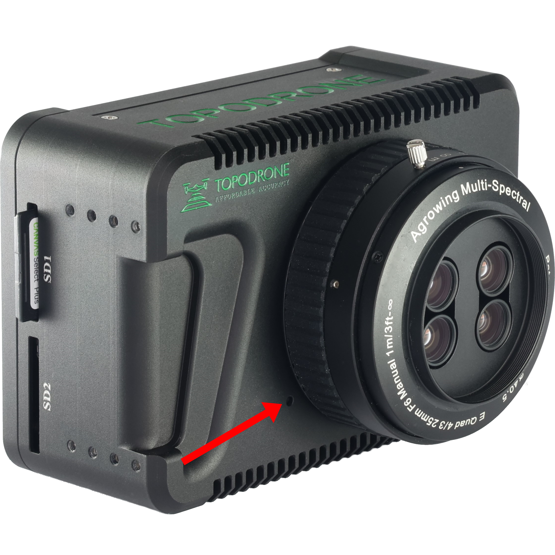
- Press the lens lock button with a thin object and remove the lens.
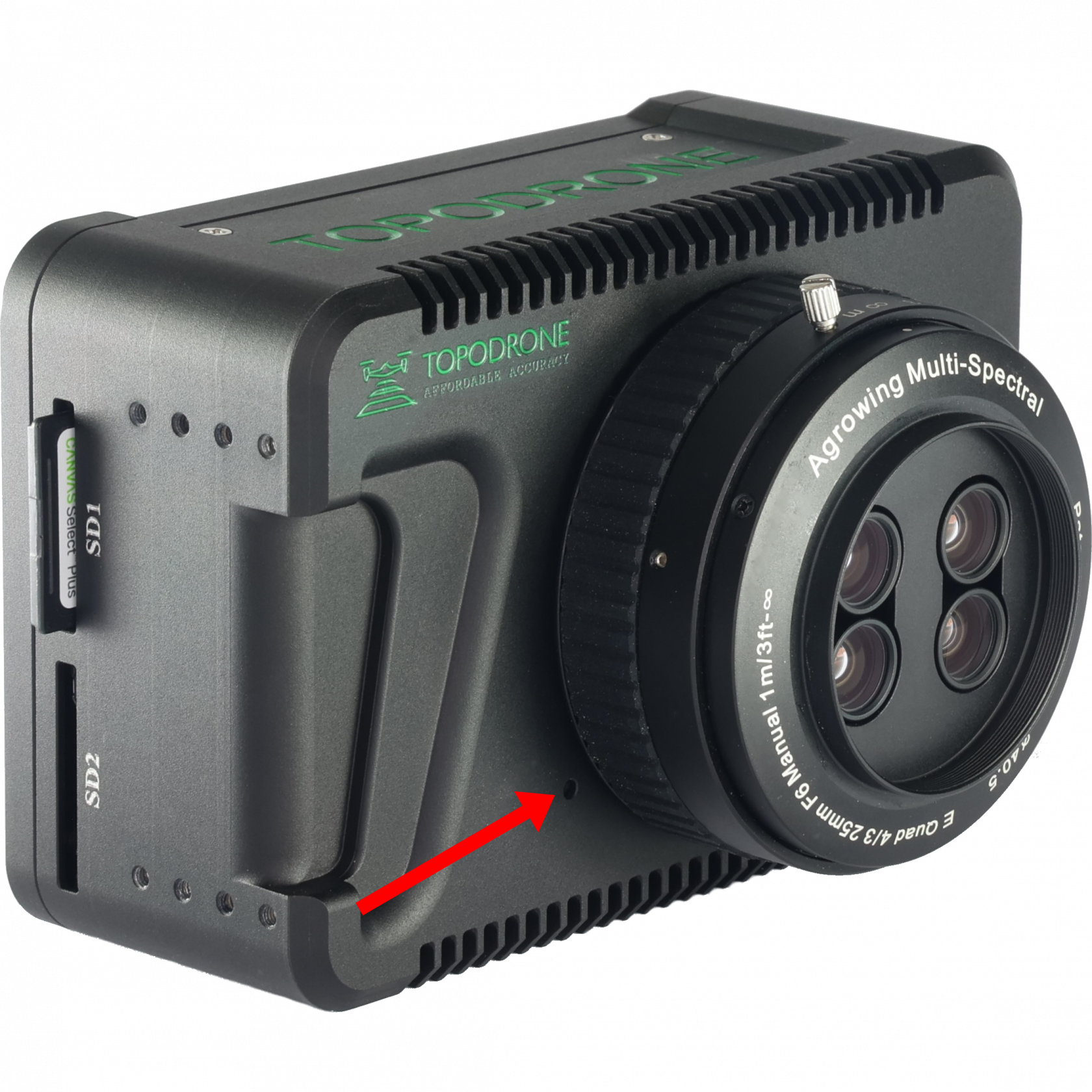
- Install the UV/IR Magnetic Clip-In Filter for Sony E-Mount.
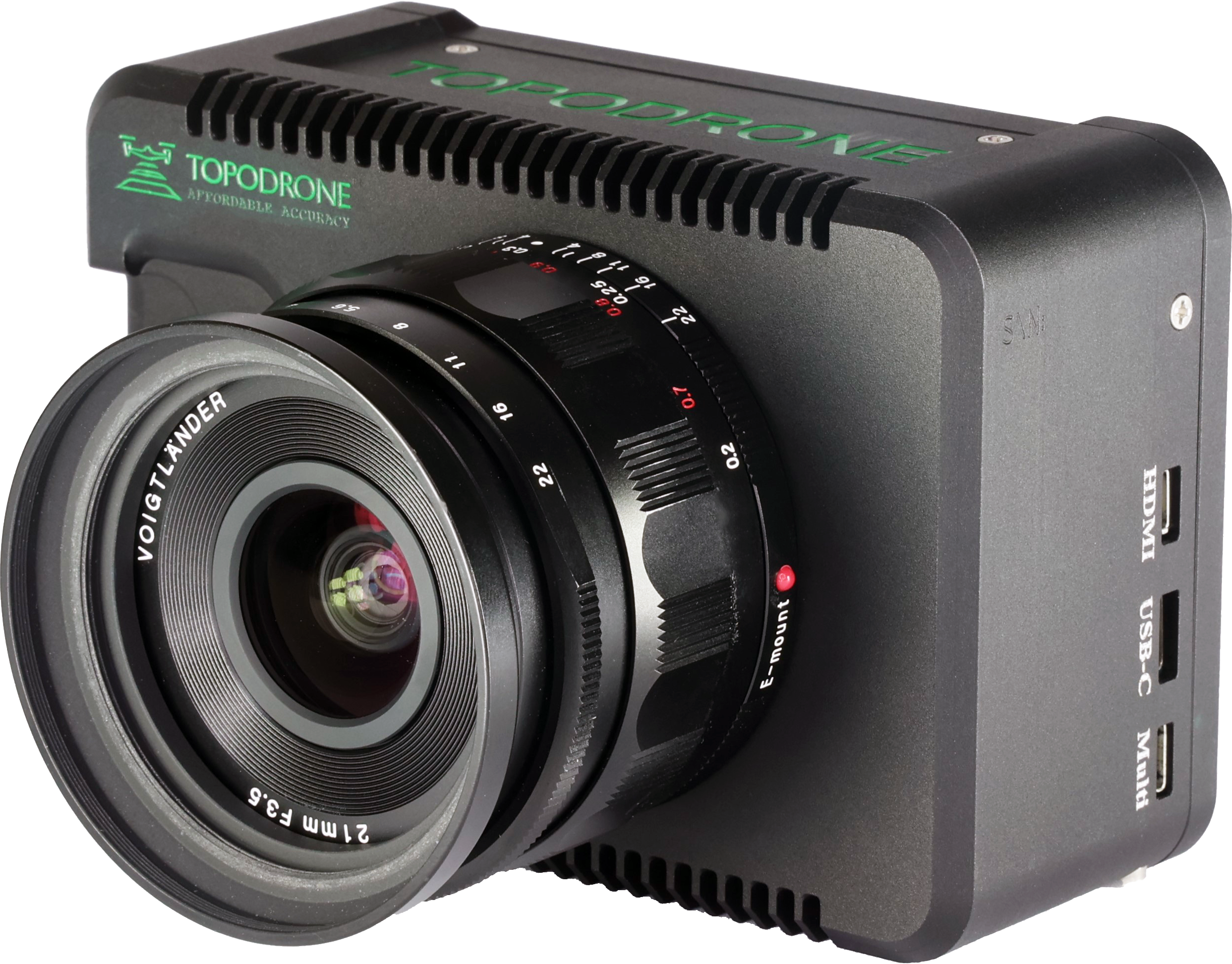
- Set the lens to shoot in the visible range.
When changing the lens back, do not forget to remove the UV filter, otherwise it may be damaged by the AGROWING lens.
TOPODRONE P61 output to the Internet for diagnostics
The following components and conditions are required to output the TOPODRONE P61 camera to the Internet when performing diagnostics:
1. Mobile device (smartphone or tablet) running Android OS (Only Samsung, Honor, Xiaomi phones are tested, other manufacturers' mobile devices may not work correctly);
2. 3G/4G/5G mobile internet or Wi-Fi network with internet connection;
3. USB - LEMO 6 PIN cable (supplied with TOPODRONE P61);
4. USB cable for connection to a mobile device (supplied with smartphone/tablet);
5. TOPODRONE P61 photogrammetric camera;
6. A drone for power connection via cable from Skyport connector.
Perform the following procedure:
1. Install the TOPODRONE P61 camera on the drone according to your delivery kit.
2. Power up the TOPODRONE P61 by connecting it to the drone.
3. Wait for the camera to turn on and load.
4. Connect the USB to LEMO 6 PIN cable and the USB to mobile device cable together via the USB Type-A connector (rectangular connector).
5. Connect the USB - LEMO 6 PIN cable to the LEMO 6 PIN connector of the TOPODRONE P61 camera.
6. Connect the USB cable to a mobile device (smartphone or tablet) running Android OS.
7. Make sure that your mobile device has an active Internet connection via 3G/4G/5G or Wi-Fi.
8. On your mobile device, go to the menu: settings / connections / mobile hotspot and modem / USB modem mode.
9. TOPODRONE P61 camera is connected to the Internet.
Adjusting the image settings
To obtain quality images, you must adjust the camera image. In case of incorrect settings, images from TOPODRONE P61 camera may be unsuitable for further photogrammetric post-processing. The final parameters are always individual, as they depend on the current lighting conditions, speed and altitude of the drone.
To obtain high-quality and correct images from the TOPODRONE P61 photogrammetric camera using the AGROWING multispectral lens, it is recommended to use the following parameters:
Shooting mode: Shutter speed priority
Shutter time: 1/1000 - 1/4000
ISO: Auto
White Balance: Auto
Set the auto continuous focus mode (AF-C)
Switch off autofocus when the shutter is turned on
Set the camera to Single Shooting mode
Turn off the Automatic Review
Set high quality photos
Adjusting the parameters using the Smart Controller
После включения вашего летательного аппарата на камеру поступит электропитание, она пройдет инициализацию и отобразится в приложении DJI Pilot 2 как полезная нагрузка TOPODRONE.
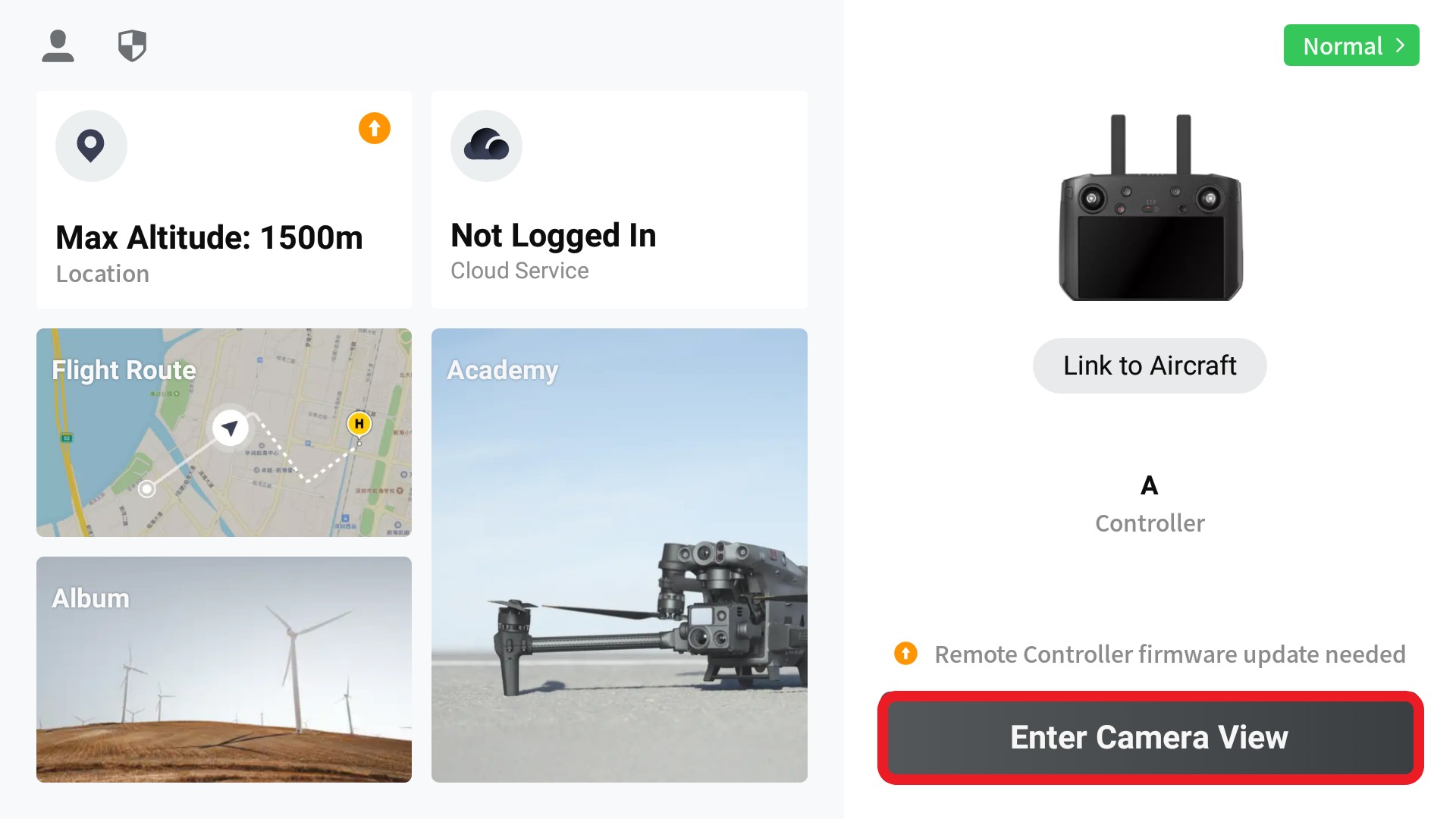 |
Step 1: Launch the DJI Pilot2 software. Make sure the software recognizes the drone and payload type
Step 2. Select “Enter Camera View”, then the “Prepare for Flight” window will open, after closing this window, the Topodrone P61 camera view will be displayed
Step 3. Make sure that there is a live video stream from the camera. |
|
| Step 4. Open the camera settings menu by clicking on the Three Dots button. | Step 5. The TOPODRONE P61 camera payload menu opens | |
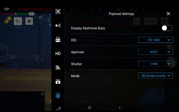 |
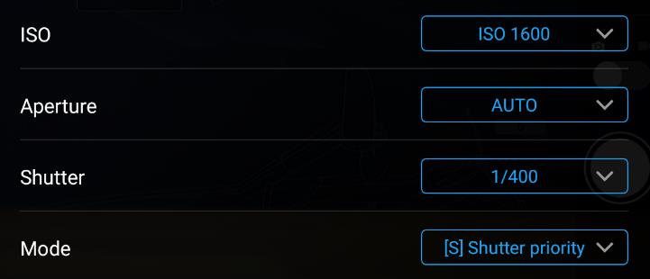 |
|
| Step 6: Adjust the 4 main image parameters: Light Sensitivity, Aperture, Aperture and Shooting Mode. | Step. 7 | |
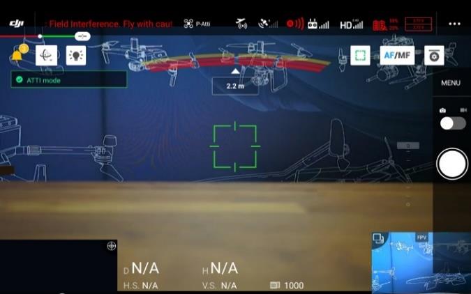 |
 |
 |
| Step 8: Close the menu and in AF (autofocus) mode, tap in the middle of the screen to focus the image. It is recommended to perform this step while flying on the ground from the mission operating altitude. | Step 9. Change the focus type from AF to MF. In this case all photos taken by TOPODRONE P61 will have the same focus value. This is important for correct photogrammetric post-processing | |
Configuring shooting settings using a Wi-Fi connection
After the camera is turned on, an access point with the name of the Wi-Fi network TD_61mp will appear, to which you can connect using the password: topodrone.
After the connection has been successfully completed, in the browser window you should enter the address: 192.168.10.1
The Main menu displays the current camera settings and the video stream.
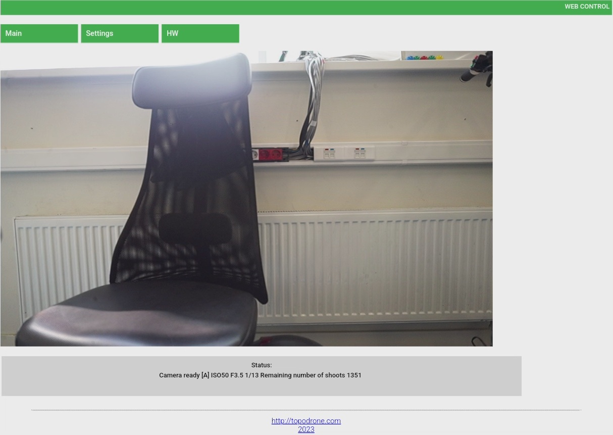
|
[S] |
MF |
ISO400 |
1/30 |
N/A |
0.0 |
microSD[1696] |
ZOOM 0% |
|
Operating Mode
Available values:
|
Focus Mode
Available values:
|
light sensitivity
Available values: 50...51200, Auto |
Shutter speed
|
Aperture value F
|
Exposure Correction
|
Number of remaining photos
|
Optical zoom value Available values: 0-100, magnification depends on the lens |
On the Settings tab, you can change the camera settings described in the previous step.
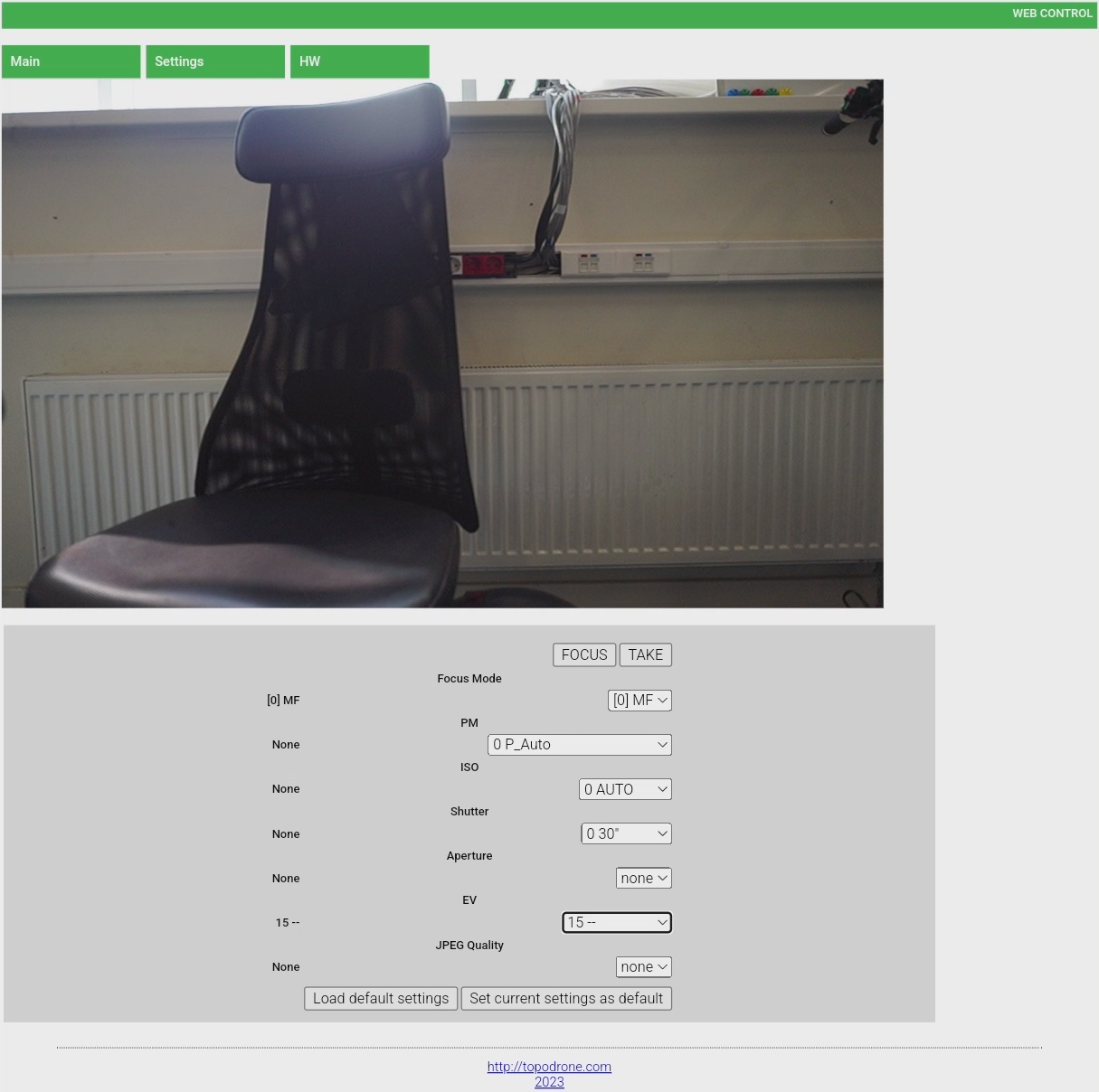
The following options are available on the settings page:
FOCUS - When pressed, the camera will focus. Available in autofocus mode only.
TAKE - The shutter button. When pressed, the camera will take a picture.
Focus Mode - Selects the focus mode (manual or auto).
PM - selection of operating mode, S - shutter speed priority, M - manual, A - aperture priority, P - program auto.
ISO - light sensitivity.
Shutter - shutter speed.
Aperture
EV - exposure step change.
JPEG Quality - JPEG quality. Available values: Fine/X.Fine/RAW.
Current values of camera parameters are displayed in the left column.
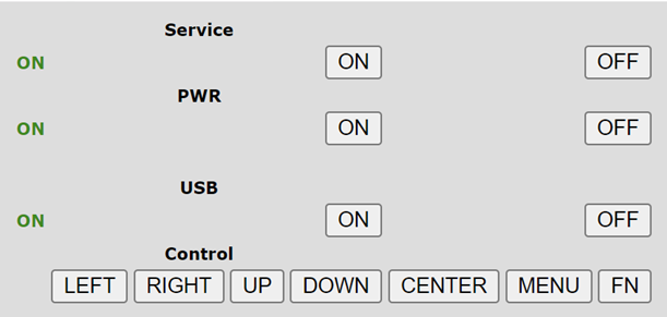
On the HW tab, use the buttons to navigate through the TOPODRONE P24 menu. This requires an HDMI connection to an external monitor. Use the HW tab only for special user settings.
Memory card: recommendations, installation, data uploading
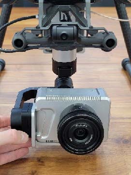
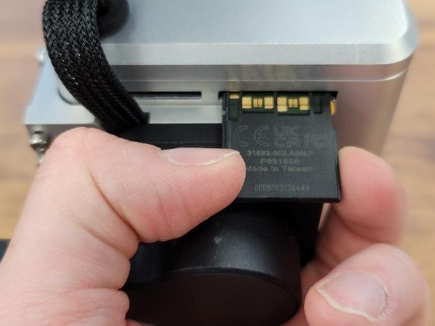
TOPODRONE P61 uses SD XC-II memory cards as the internal storage medium. Due to the high resolution of images and the high frequency of photography, it is recommended to use only SD XC-II format memory cards. A distinctive feature of the SD XC-II format is the presence of the second row of pins. Turn off the power to the drone. Lower the camera in the Pitch axis by 90 degrees. Remove the memory card.
 |
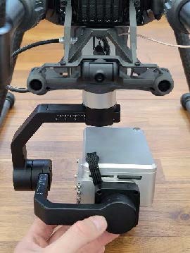 |
| Step 1: Turn off the drone's power, make sure that the suspension does not work. |
Step 2: Turn and tilt the camera with the lens facing downward as shown in the photo |
 |
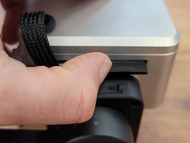 |
| Step 3: Press the memory card with your finger until it clicks into place. | Step 4: Remove the memory card by pulling it toward you. |
Do not delete all files or format the memory card. To clear free space, delete only image files in the format .JPEG from the DCIM folder. Deleting the file structure on the memory card may cause the device to malfunction.
Requirements and operating conditions
TOPODRONE Р61 is designed for use in open areas in weather without precipitation.
Do not operate the TOPODRONE Р61 in rain, snow, sleet, hail or fog.
TOPODRONE Р61 does not have IP protection, and if this recommendation is violated, moisture may get on the surface of the camera lens and inside the device. This may degrade the data received quality, as well as damage the internal structure of the TOPODRONE Р61. If precipitation starts during the flight, we recommend to stop operating, land the drone, and wipe it with paper towels and put it in the transportation case.

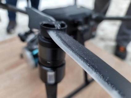
Icing of the drone during flight at -18 ° C Icing of the DJI M200 propeller
Operating TOPODRONE P61 in sub-zero temperatures and high humidity (above 80%) can lead to icing of the equipment and drone. This may deteriorate the quality of the acquired data, as well as cause damage to the structure of TOPODRONE P61 in case of falling due to icing of the supporting propellers. It is strongly recommended to warm up the device for 3-5 minutes in a warm room before starting the operation.
Application of TOPODRONE P61 for water surface photography is not effective due to small number of connecting points on water surface at the stage of photogrammetric post-processing.
For correct post-processing of data it is necessary to perform at least 4 parallel flights with side and frontal overlaps of at least 65% relative to each other. Performing the route in one or two flights is not efficient and will result in large distortions and low accuracy of the final materials. The recommended flight speed is 5 to 15 m/s depending on the height, the size of the frontal overlaps.
In case of insufficient quality or complete absence of GNSS signal, operation of TOPODRONE P61 makes no sense. The minimum number of visible satellites is 8. It is strongly recommended to check the weather conditions and the number of visible (caught) GNSS satellites before the flight, for example, in the UAV Forecast service.
Operation of TOPODRONE P61 requires careful attitude to the main lens of the camera lens. Do not allow sand, dirt, dust, water, metal chips and other fluid, abrasive and chemically active substances to get on any components of TOPODRONE P61.
The manufacturer is not liable for any damage to the equipment if it is used outside the recommended operating conditions.
Multispectral data processing TOPODRONE P61
Obtaining orthophoto using data collected from the photogrammetric camera TOPODRONE P61 with AGROWING lens is performed in several stages:
1. Obtaining high-precision photo centers in TOPODRONE Post Processing program;
2. Separation, alignment and export of multispectral images by necessary channels in AGROWING Basic program;
3. Photogrammetric processing in Agisoft Metashape program.
TOPODRONE Post Processing
Open TOPODRONE Post Processing program on the PPK Post Processing tab, select the necessary files from your flight, GNSS antenna offsets, base station file, coordinate system and specify the exact coordinates of the base station taking into account the antenna phase center.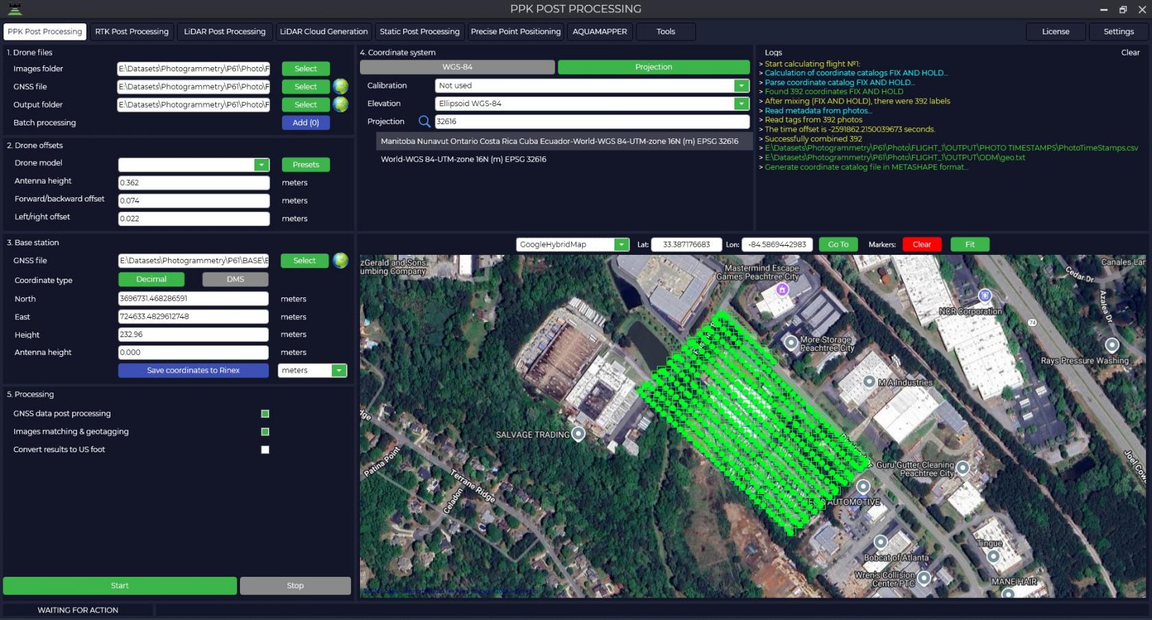
Go to the “Settings” tab and select the “Aerial Photography” section. Configure the necessary settings, making sure to check the “Tagging” and “LBH” items.
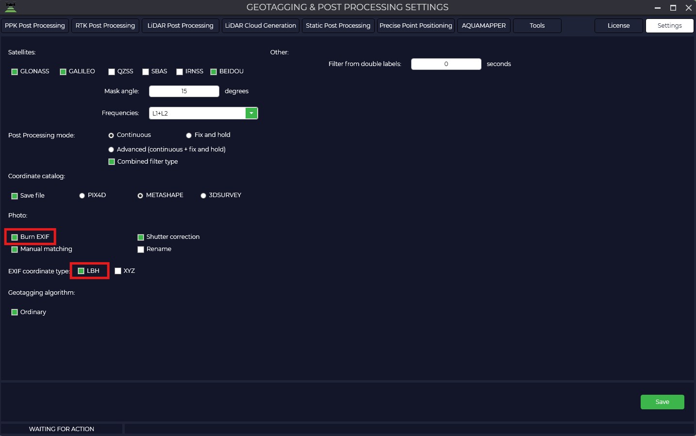
Start the processing. The result of processing will be a trajectory, a directory of exact photo centers and the photos themselves with changed tags, located in the “OUTPUT” folder called “UpdateTags”.
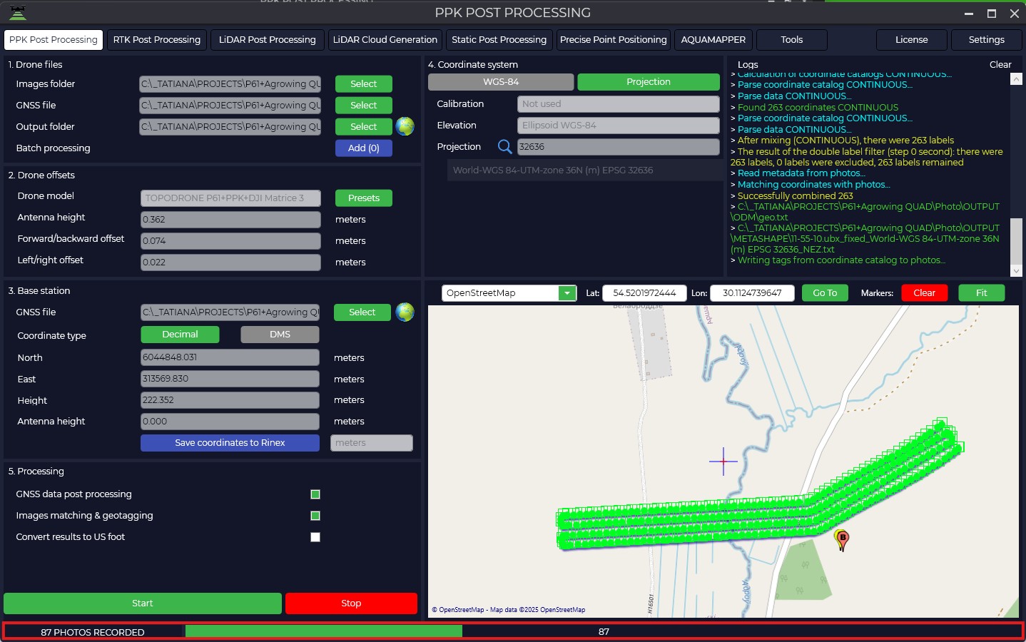
More details about the module itself can be found in the instructions for the TOPODRONE Post Processing.
Agrowing Basic
Agrowing Basic is available for users with any level of training. The program interface is intuitive, and support and tutorials will help you quickly learn all the functions. The Agrowing Basic software is free of charge and available for download at the following link: Agrowing Basic.
This section describes the processing in AGROWING Basic. For more detailed information on the program itself, please see the user manual for the program itself.
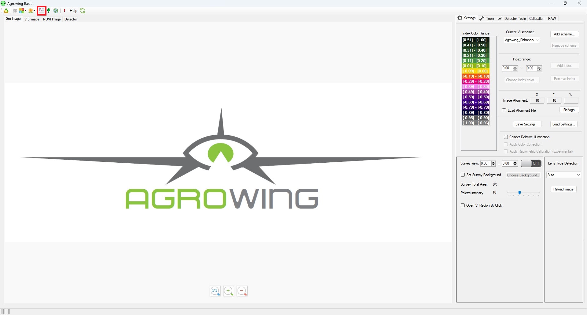
1. Start the AGROWING Basic program. Select “Image Batch Runner” item on the toolbar.
2. Select the path to the directory containing your photos and modified geotags.
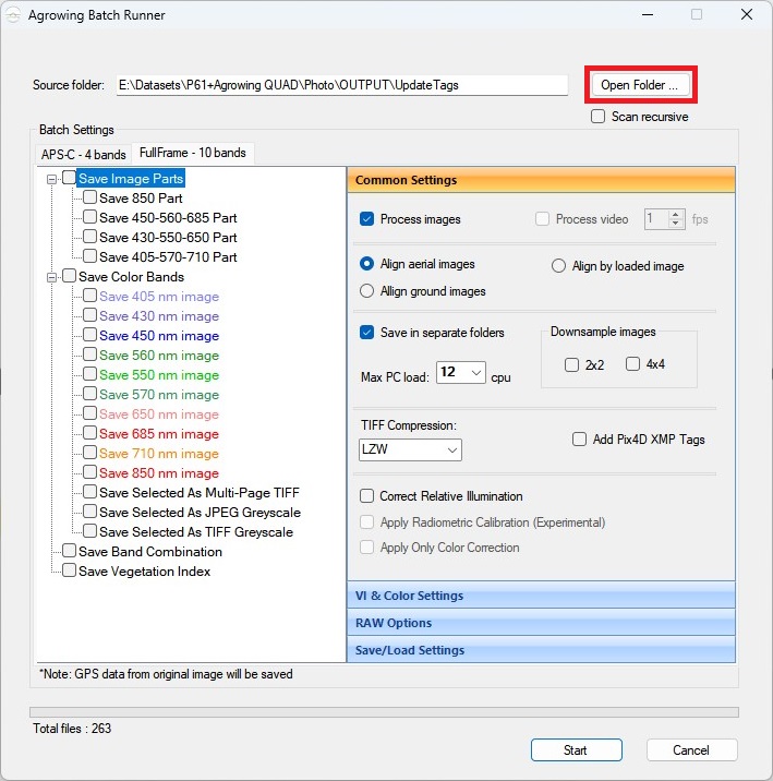
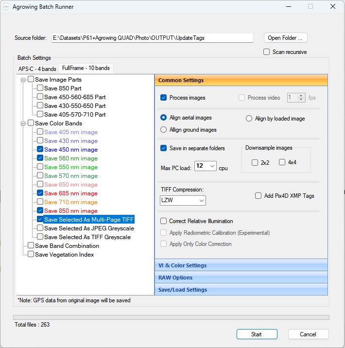
3. Select required spectral channels and type of saving the result. Save Selected As Multi-Page TIFFF allows you to export a multi-layer image containing 4 channels for each image.
General Settings:
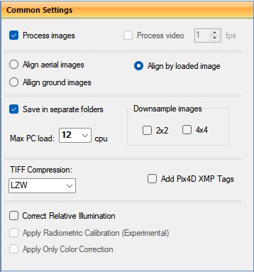
Align aerial image - quite a long process, images are aligned independently.
Align by loaded image - the application selects an random image and applies the result of aligning this image to all other images. The process is fast, but may be less accurate on some images from the same set due to small differences in heights and angles.
Align ground images - aligns images taken from the ground at a close distance of 1-1.5 meters from the object.
Save in separate folders - save results in separate folders.
Max PC load - maximum number of used streams.
Downsample images - reduce resolution of images.
TIFF Compression - select TIFF compression type from the drop-down list.
Add Pix4D XMP Tags - add tags for Pix4D program.
Correct Relative Illumination - correct relative illumination.
Apply Radiometric Calibration (Experementsl) - apply radiometric correction.
Apply Only Color Correction - apply color correction.
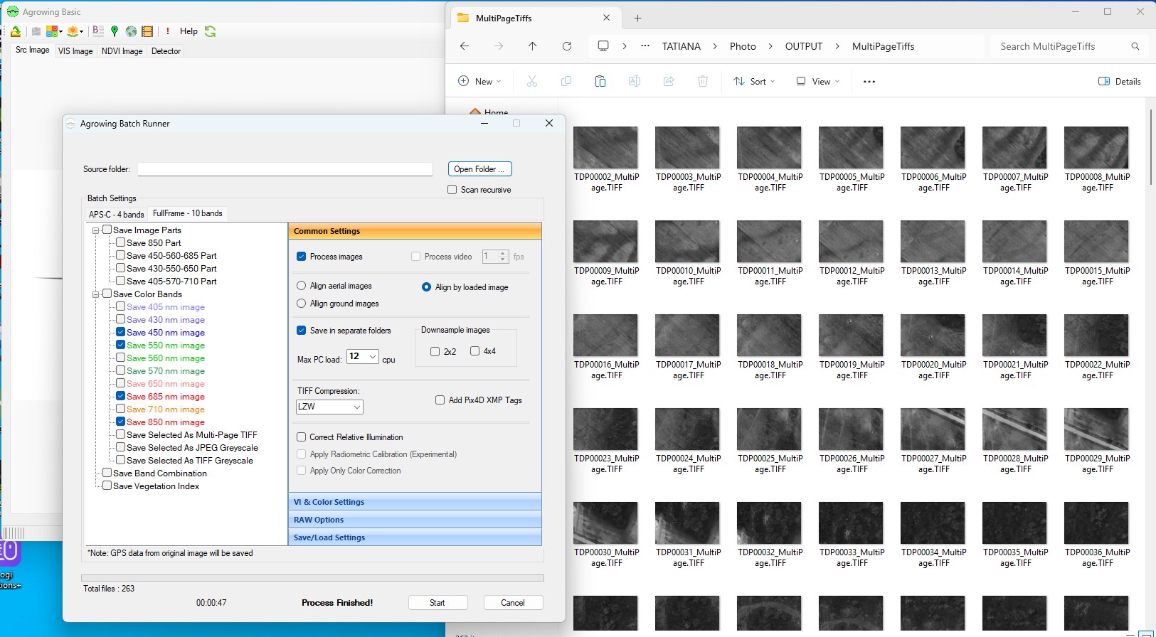
4. After making all settings, click the “Start” button. The result of processing are images in .TIFF format with exact coordinates of photo centers in xmp.
Agisoft Metashape
The process of multispectral data processing in Agisoft Metashape software has much in common with classical photogrammetric processing. Below is a detailed description of this process.
1. Open Agisoft Metashape program and select the folder where the acquired multispectral data are stored.
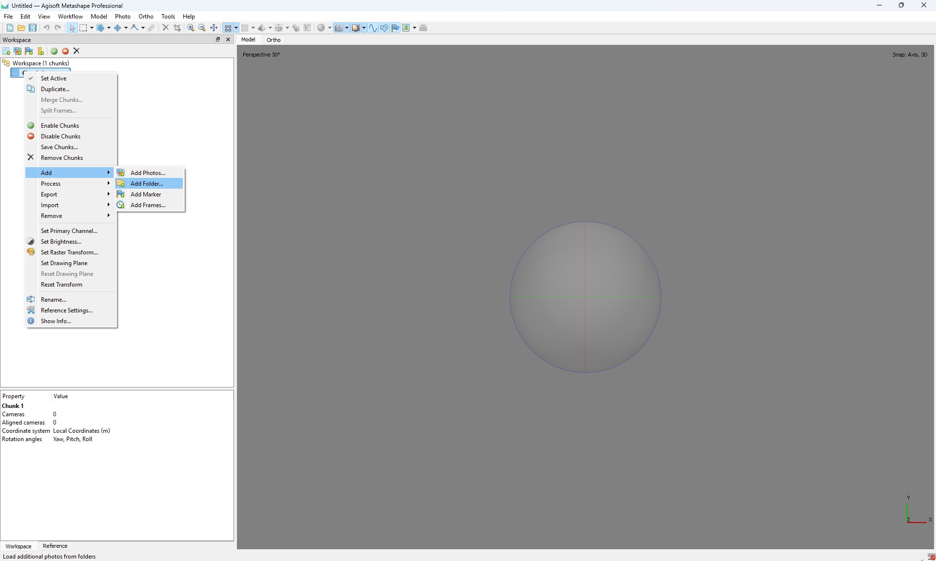
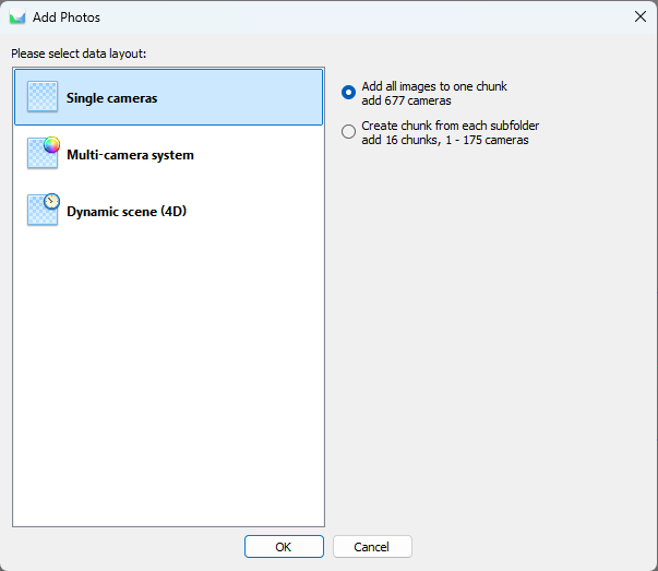
2. In the program interface, select the “Multi-camera system” option for correct data processing.
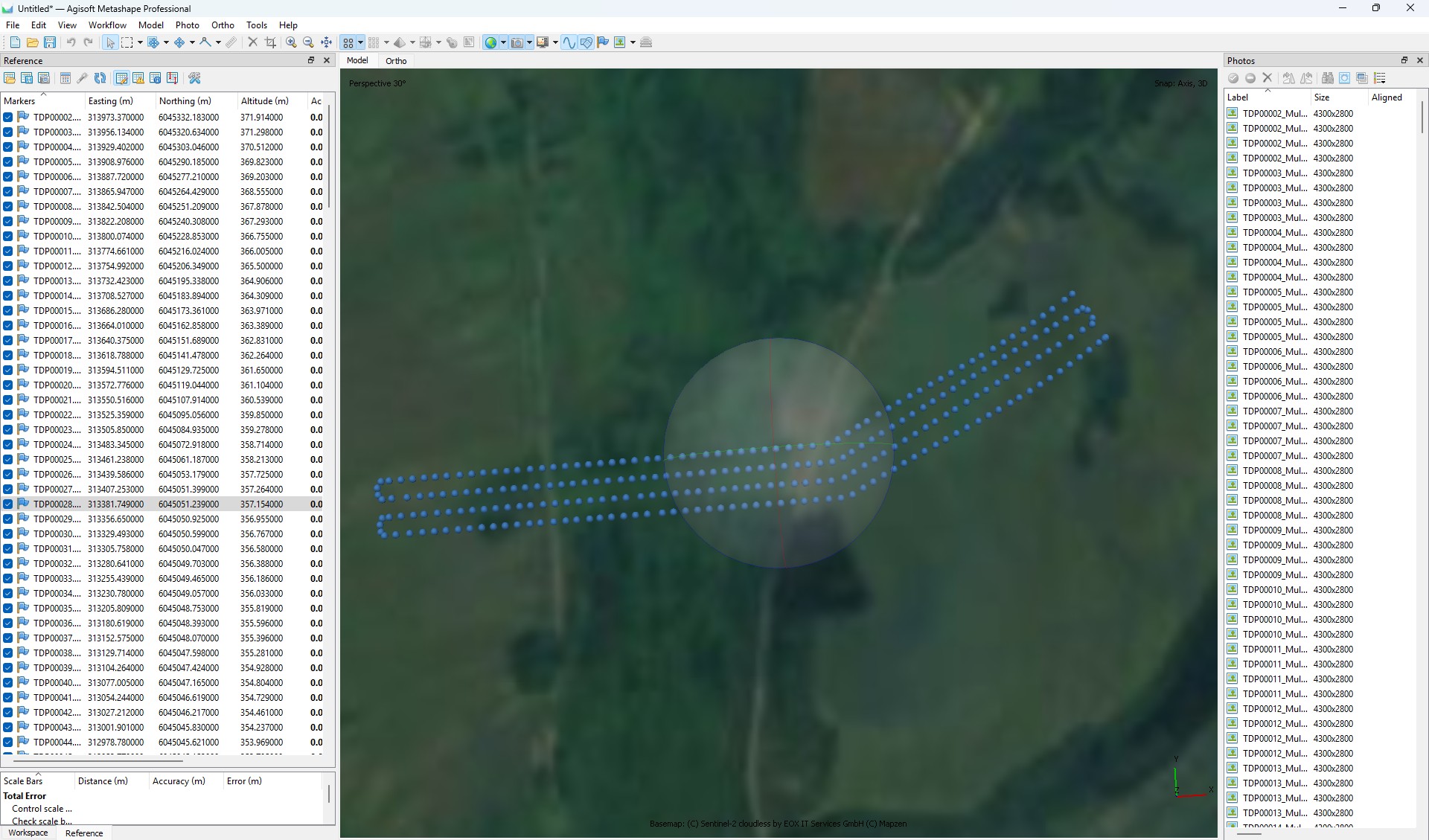
3. Open the Snap window and perform the following steps:
- Convert the photo centers to the local coordinate system;
- Set the coordinate accuracy according to the requirements of your task;
- Make sure that all cameras are correctly georeferenced to the local coordinate system.
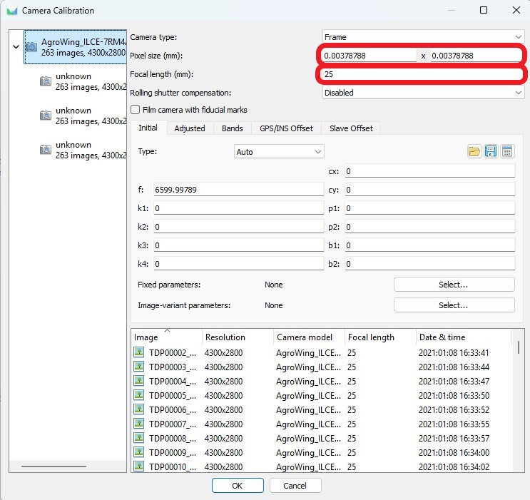
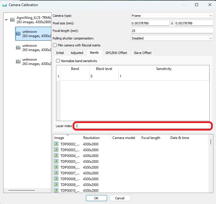
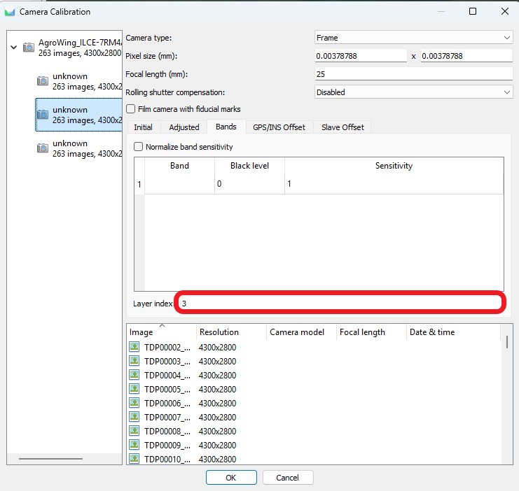
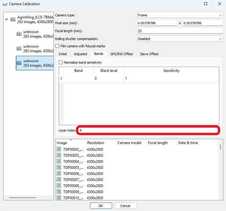
4. Go to “Camera Calibration” and follow the steps below:
- Set the physical pixel size and focal length;

- Set the sequence numbers of all multispectral channels.



5. When camera calibration is complete, perform the aerotriangulation process. This process includes:
- Create tie points based on the data from the cameras;
- Defining and refining aerotriangulation parameters to improve model accuracy.

After the aerotriangulation stage you can filter points based on the selected parameter using the “Model” tab, “Smooth selection” item.
6. Open the “Bounding” window and perform the following actions:
- Import control points in the project coordinate system;
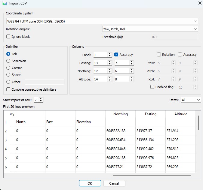
- Perform control point measurements on at least 6-9 images.

Adjust the focal length if necessary.
If the measurement accuracy meets the specified criteria, proceed to point cloud creation. Otherwise, analyze all steps of the process, from data collection to data processing, to identify and eliminate possible errors.
7. Construct a dense point cloud and digital elevation model.
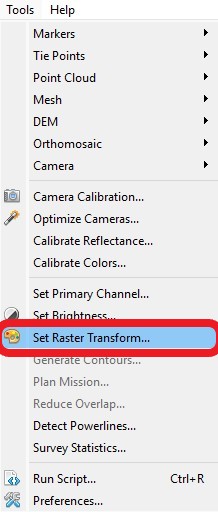
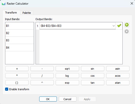
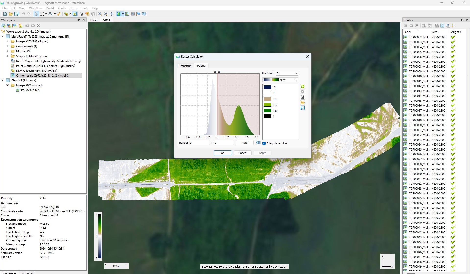
8. Compute the required index information.
- In the toolbar, use the “Set Raster Transform” button;
- In the raster calculator, enter the formula that will calculate your index;
- Go to the “Palette” tab, set the desired range, select the appropriate palette and click “OK”.
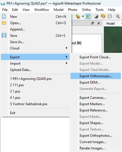
9. To export an orthomosaic, follow the steps below:
- Select “File” - “Export” - “Export Orthomosaic”
- Select the path and file name for saving the orthomosaic;
- Configure export settings following the recommendations on the screenshot. If necessary, divide the orthomosaic into blocks for convenient further use.
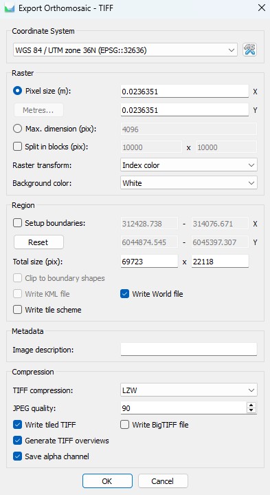
This completes the processing. All necessary materials can be exported in the same way as written in point 9.