# Settings
# General
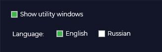
In the general settings of the TOPODRONE Post Processing program, you can perform the following actions:
Change the language of the program interface and output logs during processing.
[](https://knowledge.topodrone.com/uploads/images/gallery/2024-10/general-1.jpg)
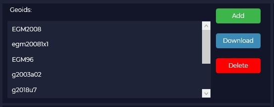
In the "Geoids" window you can add or remove the type of geoid to be used in postprocessing. If necessary, you can import another geoid in \*.gtx format. To do this, click the "Add" button and select the required file.
[](https://knowledge.topodrone.com/uploads/images/gallery/2024-10/general-2.jpg)
If necessary, you can delete a geoid model from the list by clicking the "Delete" button.
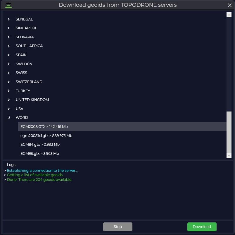
It is also possible to download a geoid model from the server. To do this, click the "Download" button, find the required geoid model and click the "Download" button.
[](https://knowledge.topodrone.com/uploads/images/gallery/2024-10/general-3.jpg)
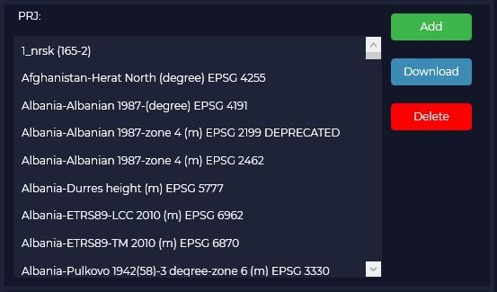
The "PRJ" window displays a list of available coordinate systems that will be available for selection during postprocessing.
[](https://knowledge.topodrone.com/uploads/images/gallery/2024-10/general-4.jpg)
You can add or remove the required coordinate system from the list. To add a coordinate system, click the "Add" button and select the desired file. Files in \*.prj formats are supported, other coordinate system formats are not supported.
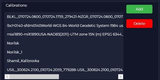
If it is necessary to delete a coordinate system from the list, click the "Delete" button. Complete deletion of imported coordinate systems is possible only after program restart. The "Calibrations" menu displays available calibration parameters, which are used for transition from one coordinate system to another.
[](https://knowledge.topodrone.com/uploads/images/gallery/2024-10/general-5.jpg)
By default, several calibration files are added for some zones. To add a calibration parameter, click the "Calibrations" button and select the desired file. Files in \*.tpc format are supported, other coordinate system formats are not supported.
# Aerial photography
Select the Aerial Photography tab to customize the processing parameters of the PPK Post Processing and RTK Post Processing modules.
[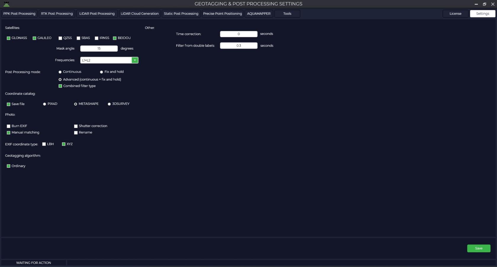](https://knowledge.topodrone.com/uploads/images/gallery/2024-10/geotagging-1.jpg)
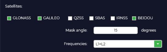
[In the "Satellites" window you can enable or disable certain satellite constellations from processing, specify the required elevation mask and select the frequencies for which you want to perform processing.](https://knowledge.topodrone.com/uploads/images/gallery/2024-08/geotagging-and-postprocessing-1.jpg)
[](https://knowledge.topodrone.com/uploads/images/gallery/2024-10/u18geotagging-2.jpg)
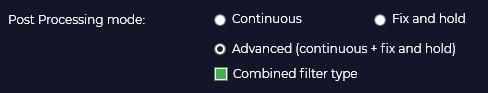
In the Postprocessing Mode window, you can select from Continuous, Fix and hold, or Advanced.
[](https://knowledge.topodrone.com/uploads/images/gallery/2024-10/geotagging-3.jpg)
In "Fix and Hold" mode, the program strives to obtain a fixed positioning solution that provides the highest accuracy and reliability. It uses information from the base station and rover to calculate the relative position and then amplifies this solution to achieve a fix. When a fix is achieved, the program holds this solution for as long as possible, even if the signal quality temporarily drops or some satellites are lost.
The purpose of the "Fix and Hold" mode is to provide a stable and reliable fixed solution, which is particularly useful in surveying applications where high accuracy and long-term stability are required. This mode may be preferred when it is important to avoid switching between solutions and to ensure continuity of the fix even in the face of temporal changes (e.g. signal reflections or passing through obstacles).
In "Continuous" mode the algorithm processes data continuously and updates positioning results as new data is received. In contrast to the "Fix and Hold" mode, here the program does not fix the solution, but continuously calculates the rover position based on the current data. When new observations are received, the program updates the position taking into account these data and previous results.
Continuous mode provides more relevant positioning results because it continuously updates the position based on the latest data. It can be useful in applications where relevance and dynamic position changes are more important.
The choice between "Fix and Hold" and "Continuous" modes depends on the specific requirements and conditions of the application. If stability and reliability of solution fixation is important, especially under static conditions, the "Fix and Hold" mode may be preferred. If relevance and dynamic positioning are more important, "Continuous" mode provides a more continuous position update based on the latest data.
The "Advanced" mode is a combination of the previous modes with all their pluses, but data processing takes a little longer.
In the "Coordinate Catalog" window, you should check the "Write File" box to save the catalog of photo centers and select the file format for the program you are using.
[](https://knowledge.topodrone.com/uploads/images/gallery/2024-10/geotagging-4.jpg)
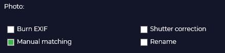
In the "Photos" window you can save the coordinates of the photo centers in the EXIF file of the photo, assign a unique name to the photos depending on the time of creation, it is recommended to check the "Manual matching" checkbox for correct matching of photos and marks, the "Shutter correction" checkbox is responsible for shifting the mark by half the shutter time.
[](https://knowledge.topodrone.com/uploads/images/gallery/2024-10/geotagging-5.jpg)
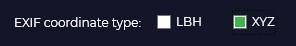
In case you checked "Write tags" in the previous window, you should select the format of coordinates saving (LBH - geographic coordinates, XYZ - rectangular coordinates).
[](https://knowledge.topodrone.com/uploads/images/gallery/2024-10/geotagging-6.jpg)
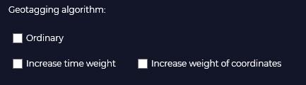
The "Geotagging Algorithm" tab contains settings to help the program match photos and tags in the event of a quantity mismatch.
Normal - the alignment is done in the order of the photos taken.
Increase time weighting - matching is based on the time the photos and tags were created.
Increase coordinates weight - Matching is performed by navigation coordinates of photos contained in tags and high-precision coordinates of tags as a result of post-processing in TOPODRONE Post Processing program.
[](https://knowledge.topodrone.com/uploads/images/gallery/2024-10/geotagging-7.jpg)
In case of routes where some photos are overlapped with other photos, the coordinate matching algorithm may not work correctly. Example: route on one battery when shooting a small object for 3D reconstruction. In the case of shooting when the camera is pointing at nadir and then immediately shooting when the aircraft is shooting perspective.
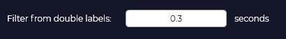
The double-tag filter allows you to remove unnecessary tags at the post-processing stage. Default value 0.2 seconds.
[](https://knowledge.topodrone.com/uploads/images/gallery/2024-10/geotagging-8.jpg)
# Lidar scanning
In this section of the program you can configure parameters for high-precision trajectory processing, point cloud generation including TOPOSLAM technology.
[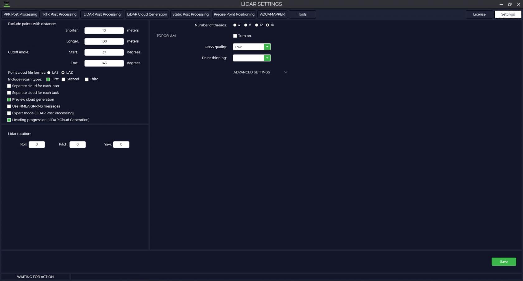](https://knowledge.topodrone.com/uploads/images/gallery/2024-10/lidar-1.jpg)
[To do this, go to the "Settings" tab, and then select "Lidar scanning" and in the window that appears, configure the processing parameters.](https://knowledge.topodrone.com/uploads/images/gallery/2024-08/lidar-scanning-1.jpg)
| [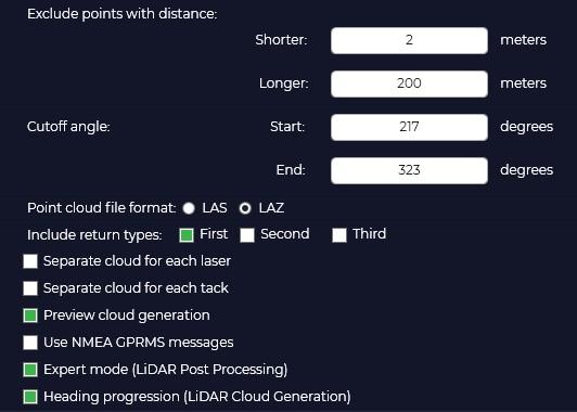](https://knowledge.topodrone.com/uploads/images/gallery/2024-10/lidar-2.jpg)
| Exclude points with distance from lidar
Closer is the distance to disregard when generating the point cloud.
Next is the maximum beam length when generating points.
Cut angle:
Specify the start and end angle of the LiDAR scan.
Point cloud format - select in which format the LAS/LAZ point cloud will be generated.
Include return types in the point cloud - select the number of reflections you need or the number that your hardware supports.
• **FIRST** – first reflection
• **SECOND** –second reflection
• **THIRD** – third reflection
Separate point cloud for each laser - generate separate point clouds for each beam separately.
Separate point cloud for each tack - generate a point cloud according to how the user divides the data into transects.
Preview cloud generation - view point cloud generation in real time
|
Synchronize time by NMEA GPRMC packets -
Expert mode (LiDAR Post Processing) is a mode that allows you to manually specify the type of sensor and IMU to be used.
[](https://knowledge.topodrone.com/uploads/images/gallery/2024-10/lidar-3.jpg)
TOPOSLAM is designed to correct the point cloud when the GPS signal is not good enough. Currently TOPOSLAM only supports ground scanning.
[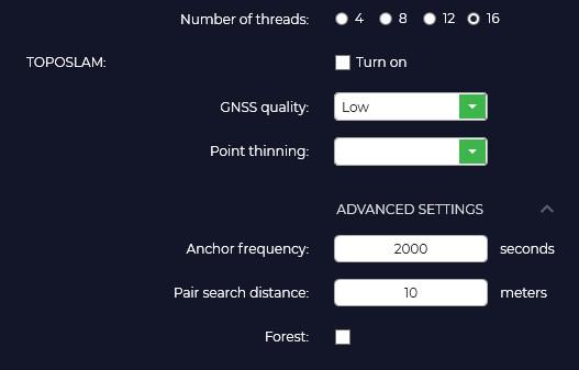](https://knowledge.topodrone.com/uploads/images/gallery/2024-10/dyLlidar-4.jpg)
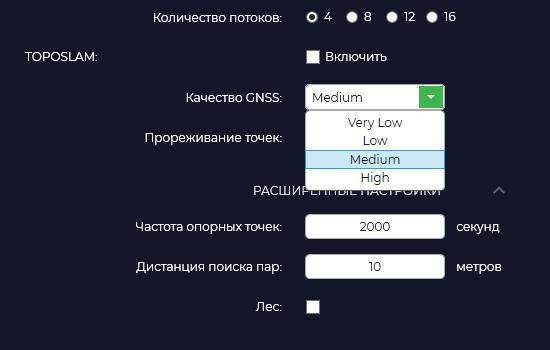
Number of streams. Specify the number of processor threads you would like to utilize to accelerate SLAM processing.
To activate the TOPOSLAM algorithm, you must check the corresponding "Enable" option.
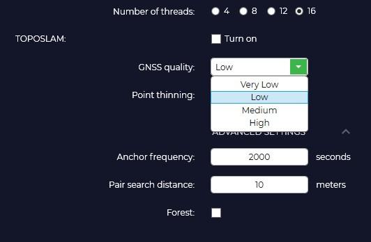
GPS signal quality. Depending on the quality of GPS track you should select the appropriate tab. Low - floating solution more than 70%, Medium - floating solution more than 50%, High - floating solution more than 20%. If the quality is low, the program splits the track into smaller segments for their further mutual comparison.
[](https://knowledge.topodrone.com/uploads/images/gallery/2024-08/lidar-scanning-4.jpg)
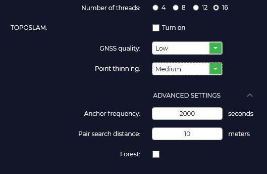
Point thinning. Segment skipping function. Off - do not skip, Low - skip one segment after each generated segment, Medium - skip two segments, High - skip four segments. This function is designed to speed up the processing process and in case of RAM shortage for large shootings.
[](https://knowledge.topodrone.com/uploads/images/gallery/2024-10/F0rlidar-5.jpg)
Frequency of reference points.
Distance search for pairs.
Forest.
[](https://knowledge.topodrone.com/uploads/images/gallery/2024-10/lidar-7.jpg)
# Laser scanner track file structure
To customize the track file structure, go to the Settings tab, then select Lidar Scanning and select the Track File Structure option from the drop-down list. In the opened window you should specify the trajectory file obtained as a result of postprocessing.
If you have performed processing in TOPODRONE Post Processing software, specify the order of the columns according to the following example:
[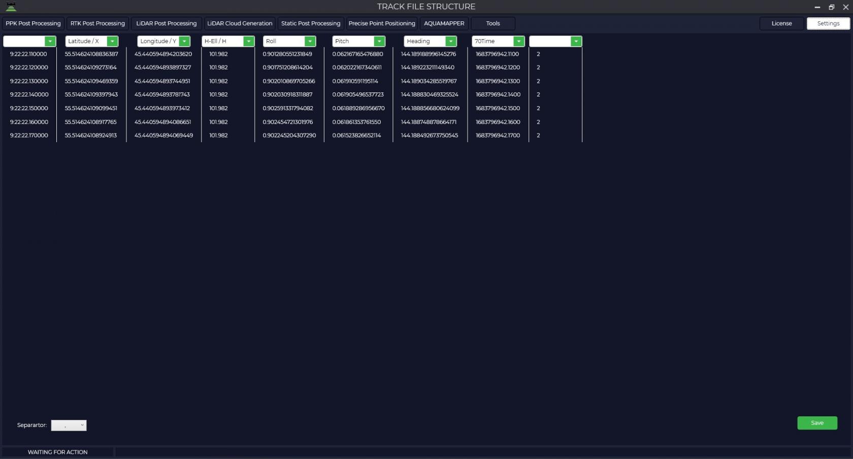](https://knowledge.topodrone.com/uploads/images/gallery/2024-10/lidar-8.jpg)
After filling in all the fields, click the "Save" button.
This procedure only needs to be performed once. If you continue to use the TOPODRONE Post Processing software, you will no longer need to specify the track file structure. However, if you have been processing in any other software, the structure of the track file will be different and you will need to specify the appropriate field order for your track file.
# Laser Scanner Sensor Beam Calibration
To set the laser scanner sensor beam calibration, go to the Settings tab, then select Lidar Scanning and select the Lidar Calibration option from the drop-down list. Then select the model of your laser scanner.
In the window that opens, you will be able to turn off unnecessary beams or adjust the necessary calibration values.
Important Note: Laser scanners manufactured by TOPODRONE are factory calibrated and do not require recalibration during their entire lifetime.
| [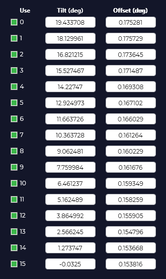](https://knowledge.topodrone.com/uploads/images/gallery/2024-08/Wq0image.png)
| Use – beam number
Tilt (deg) – beam angle in degrees
Offset (mm) – beam offset relative to the sensor in mm.
The number of lidar beams depends on the model of your laser scanner and may vary depending on the type of device.
|
# AQUAMAPPER
Select the "AQUAMAPPER" tab to configure the processing parameters of AQUAMAPPER modules.
[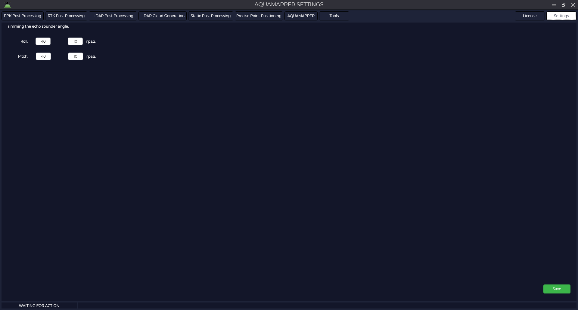](https://knowledge.topodrone.com/uploads/images/gallery/2024-11/image.png)
If necessary, adjust the Roll and Pitch angles. Closer to zero values of these angles will help to increase the share of vertical measurements in the processing process.
The optimal angle values are in the range from -8 to +8 degrees.