# TOPODRONE UAV PPK UPGRADE Kit
# Disclaimer
The TOPODRONE UAV PPK UPGRADE Kit receivers are high-precision geodetic measuring instruments. When operating the geodetic receiver, it is strongly recommended to handle it with care and caution to extend the service life of the TOPODRONE UAV PPK UPGRADE Kit. All product parameters, recommendations, limitations, field procedures, and data post-processing methods are described in this document and in the instructions for the [TOPODRONE Post Processing](https://knowledge.topodrone.com/books/topodrone-post-processing) software.
 It is PROHIBITED to operate the TOPODRONE UAV PPK UPGRADE Kit in any way not specified or described in the "User Manual" or the "Operational Guidelines".
 It is PROHIBITED to subject the TOPODRONE UAV PPK UPGRADE Kit to impact or vibration, especially when the device is on: dropping, hitting, scratching, tossing, shaking, knocking, etc.
 It is PROHIBITED to place the TOPODRONE UAV PPK UPGRADE Kit in direct sunlight, in poorly ventilated areas, or near a heat or cold source.
 It is PROHIBITED to fully or partially submerge the TOPODRONE UAV PPK UPGRADE Kit in water, or expose the product to heavy rain, snow, sand, or dust for extended periods. The TOPODRONE UAV PPK UPGRADE Kit is not structurally protected against moisture or dust ingress; therefore, using the equipment in humid (above 90%) or dusty environments may lead to malfunction, performance degradation, or corrosion processes, potentially causing device failure.
 It is PROHIBITED to insert foreign objects into the memory card slot, LEMO 6-Pin connector, or external GNSS antenna connector, nor to insert the memory card upside down, or attempt to connect incompatible connectors to the LEMO 6-Pin or antenna port.
 It is PROHIBITED to insert or remove the MicroSD memory card while the TOPODRONE UAV PPK UPGRADE Kit is operating, as this may damage the card and/or lead to data loss. To safely remove the MicroSD memory card, power off the device and wait for it to shut down.
 It is PROHIBITED to connect to the LEMO 6-PIN connector with incorrect pinout or voltage/current characteristics not described in this manual.
 It is PROHIBITED to open the external cover of the TOPODRONE UAV PPK UPGRADE Kit.
 When the TOPODRONE UAV PPK UPGRADE Kit is not in use, it is recommended to store the device indoors, at a relative humidity not exceeding 40% and a temperature of 20±5°C.
 If moisture gets onto the TOPODRONE UAV PPK UPGRADE Kit during operation due to rain, snow, or fog, wipe it with a clean, dry paper or microfiber cloth. Then leave it in a dry room for an hour to dry completely. After that, place the TOPODRONE UAV PPK UPGRADE Kit in its storage or transport location. For long-term storage, a small silica gel packet can be used to absorb moisture.
 The TOPODRONE UAV PPK UPGRADE Kit operates using PPK technology and requires GNSS data from a base station for the duration of its operation for data post-processing.
 To obtain correct data from the TOPODRONE UAV PPK UPGRADE Kit, a quality GNSS signal is required during operation, for both the geodetic receiver and the base station.
 In the event of intentional or accidental violation of any of the requirements described above, the manufacturer does not guarantee the functionality of the TOPODRONE UAV PPK UPGRADE Kit.
# Product Specifications
#### **Product Description**
The TOPODRONE UAV PPK UPGRADE Kit is a versatile geodetic GNSS receiver developed on the basis of a u-Blox chip for integration with cameras on various UAVs to obtain high-precision coordinates of image centers. To operate the TOPODRONE UAV PPK UPGRADE Kit, an external GNSS antenna must be connected to receive satellite signals, as well as external power and a signal line from the camera shutter. For connection convenience, the power and signal line are combined in a LEMO connector, while the antenna connector is separate.
The main task of the TOPODRONE UAV PPK UPGRADE Kit is to record raw GNSS measurement data from the external antenna along with the precise timestamp of the connected camera's shutter trigger on the UAV. The output file is a file with the \*.ubx extension, which is written to an external storage medium – a MicroSD memory card. The TOPODRONE UAV PPK UPGRADE Kit operates based on Post Processing Kinematic (PPK) technology. To enable post-processing of the acquired data, it requires a static measurement file from a base station for the same operating period and location. The precise shutter trigger time is synchronized with the base station's operating time using GPS time. The results of post-processing the data obtained from aerial surveying with the TOPODRONE UAV PPK UPGRADE Kit in the TOPODRONE Post Processing software are high-precision coordinates of the image centers.
The TOPODRONE UAV PPK UPGRADE Kit is compatible with TOPODRONE-brand cameras (P24 and P61) as well as with third-party cameras: DJI X4S, Sony A6000, Sony A7RM4, etc. To connect to TOPODRONE cameras, a special cable from the camera with a compatible LEMO connector is used in some cases. To connect third-party cameras, the shutter signal option is used via an external flash connection through the camera's Hot Shoe connector. The TOPODRONE UAV PPK UPGRADE Kit can also register external pulses to record the precise shutter trigger time.
The TOPODRONE UAV PPK UPGRADE Kit starts data recording when external power is connected and any GNSS signal is present after the initialization procedure. If the external GNSS antenna is disconnected, or if the device is turned on without an external GNSS signal, data recording to the external storage medium does not start.
#### **Package Contents**
1. 1 pc. TOPODRONE UAV PPK UPGRADE Kit Geodetic GNSS Receiver
2. 1 pc. MicroSD 16 GB Memory Card
3. 1 pc. LEMO 6-Pin Connector (optional, with or without cable)
4. 1 pc. Cable with LEMO 6-Pin – LEMO 4-Pin Connector
5. 1 pc. Antenna Cable with Connector (optional)
6. 1 pc. GNSS Antenna Mount with cable and mounting screws for UAV (optional)
7. 1 pc. External GNSS Antenna (optional)
#### **Device Construction**
Structurally, the TOPODRONE UAV PPK UPGRADE Kit is manufactured in a compact housing made of aluminum alloy with anodizing (optional). Geometric dimensions in mm are shown in the dimensional diagram below. The housing has a cover fastened with screws to the main housing for access to internal components.
| [](https://knowledge.topodrone.com/uploads/images/gallery/2024-03/LX6image.png)
| [](https://knowledge.topodrone.com/uploads/images/gallery/2024-03/7Iyimage.png)
|
1. LEMO 6-Pin connector for external power and camera shutter signal
2. Green LED. Indicates external power is present.
3. Blue LED. Indicates GNSS antenna signal quality:
| **Состояние**
| **Описание**
|
| Off | PDOP>10 |
| Slow blinking | 3<PDOP<10 |
| Fast blinking | 2<PDOP<3 |
| Continuously on | PDOP<2 |
PDOP is a factor indicating the reduction in GNSS receiver positioning accuracy relative to the geometry of satellite positions in the sky. The operator can determine its value from the LED indicator table above and assess the feasibility of surveying. The lower the PDOP value, the more accurate the position calculation result. PDOP is considered very high at 3 or more; it is not recommended to perform aerial surveys with high PDOP values.
4. Orange LED. Indicates the recording status to the MicroSD memory card. During recording, the LED blinks rapidly. Each blink corresponds to 4 KB of data written.
5. Red LED. Lights up continuously together with the other LEDs. Indicates an error during data writing to the memory card. In case of an error, check the memory card for errors, format it to FAT32, or replace it with another memory card.
If replacing, reconnecting, or formatting the MicroSD card does not resolve the issue, contact TOPODRONE technical support.
6. MicroSD memory card slot
7. Coaxial cable for connecting an external GNSS antenna
8. Enclosure cover
9. Enclosure body
10. Enclosure cover screws
Each time the receiver is turned on, a new \\\*.ubx file is created in a folder named in the DD-MM-YY (day-month-year) format, with a file name in the HH-MM-SS (hours-minutes-seconds) format. Note that the time is recorded in UTC, and the file is created only after the GNSS receiver acquires a signal from satellites.
It is forbidden to insert or remove the memory card while the receiver is operating. This operation should only be performed when the power is disconnected.
In the standard configuration, the GNSS receiver records a \\\*.ubx file at a frequency of 10 Hz and receives signals from GPS, GLONASS, Galileo, and Beidou systems on L1 and L2 frequencies.
# External GNSS Antenna Offsets
During post-processing to obtain a high-precision trajectory of the aircraft, the GNSS antenna phase center is used. However, to obtain image coordinates, the coordinates of the image centers must be used. Since these two points do not coincide and have certain displacements, these displacements are called GNSS antenna offsets.
To determine the offsets, it is necessary to measure the relative displacement of the antenna's phase center position along three axes: X, Y, and Z. The diagram below shows the relative arrangement of the X, Y, and Z axes.
If the image center is located in front of, below, and to the left of the GNSS antenna along the direction of travel, the offset values during post-processing are entered in the TOPODRONE Post Processing software as positive values (without a minus sign) in meters.
If the image center is located behind, above, and to the right of the GNSS antenna along the direction of travel, the offset values during post-processing are entered in the TOPODRONE Post Processing software as negative values (with a minus sign) in meters.
[](https://knowledge.topodrone.com/uploads/images/gallery/2024-03/CVeimage.png)
One convenient method for measuring offsets is to securely place the UAV on a level floor or table, with its nose flush against a flat vertical wall of the room. All necessary measurements in this case are taken relative to the floor (or table) and the wall, respectively.
The image center is the geometric center of the camera's main sensor, located at the intersection of the diagonals of the rectangular sensor.
Many photographic equipment manufacturers indicate the sensor plane position on the camera body, significantly simplifying the determination of the image center position. The adjacent example shows the sensor plane marking on a Sony A7R4 camera. If such a mark is not present, the depth of the sensor position can be measured with a caliper or ruler after removing the lens. It is essential to place a lint-free cloth or a small piece of tissue between the sensor and the measuring tool's depth rod. After measuring the sensor plane depth, it is convenient to take measurements from the lens bayonet edge to the floor.
It is recommended to blow dust off the sensor only using a specialized rubber blower or compressed air canister for cleaning photo equipment. It is not recommended to blow into the camera with your mouth, as saliva particles may land on the sensor and leave stains.
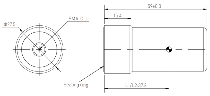
The position of the phase center differs for each model of GNSS antenna. The most frequently used GNSS antenna by TOPODRONE is the **Harxon HX-CH6601A**. The L1/L2 satellite signal frequency phase center of this GNSS antenna is located 37 mm from the bottom plane, exactly at the center. Thus, it is convenient to measure offsets to the base of the GNSS antenna mount.
If another model of GNSS antenna is used with the UAV alongside the TOPODRONE UAV PPK UPGRADE Kit, the height of the phase center must be verified in the manufacturer's technical documentation.
| [](https://knowledge.topodrone.com/uploads/images/gallery/2024-03/embedded-image-jyubgsax.png)
| [](https://knowledge.topodrone.com/uploads/images/gallery/2024-03/embedded-image-0qhotp8a.png)
|
If another model of GNSS antenna is used with the UAV and the TOPODRONE UAV PPK UPGRADE Kit, the height of the phase center must be verified in the manufacturer's technical documentation.
# Connection Diagram and External Pulse Characteristics
- For connection convenience, a LEMO 6-PIN connector is used. The pinout and description of the LEMO 6-PIN connector are provided below:
- GND – Ground
- 3V3 – Output line of regulated external 3.3V power
- Time Mark – Input signal line for camera shutter trigger
- Vin (5..18V) – Receiver input power from 5V to 18V
- Shot control (for Sony cameras) – Output signal for controlling Sony camera shutter
- n/a – Not assigned

When the TOPODRONE UAV PPK UPGRADE Kit is powered on and has completed initialization, it expects Falling Edge type pulses on the TimeMark pin, indicating the shutter trigger moment. The external pulse duration must not exceed 20ms. The TOPODRONE UAV PPK UPGRADE Kit also has an internal pull-up resistor, pulling the pulse voltage level to 3.3V.
# TOPODRONE UAV PPK UPGRADE Kit Technical Specifications
| Supported GNSS Systems & Frequencies
| GPS: L1C/A, L2C;
GLONASS: L1OF, L2OF;
GALILEO: E1B/C, E5b;
BEIDOU: B1I, B2I
|
| Raw Measurement Logging Frequency, Hz | 10 |
| Number of GNSS Receiver Channels | 184 |
| Supported Memory Card Formats | microSD, microSDHC, microSDXC |
| Maximum Supported Memory Capacity | 32 |
| Supported File System Type | FAT32 |
| Minimum Number of Satellites for Initialization | 8 |
| Dimensions (W×D×H), mm | 65 x 43.2 x 18 |
| Weight (without LEMO connector), g | 46 |
| Operating Temperature Range | от -20°C до +60°C |
| Storage Temperature Range | от -40°C до +60°C |
| Operating Humidity Range | от 20% до 95% |
| Country of Origin | Switzerland |
| Maximum Base Station Range, km | 25 |
| Recommended Base Station Range, km | 10 |
# FAQ
**Why TOPODRONE UAV PPK UPGRADE Kit does not initialise?**
The UAV may be in a location with poor GNSS reception. It is necessary to place the UAV with TOPODRONE UAV PPK UPGRADE Kit in a more open area and provide the GNSS antenna with visibility of at least 8 satellites for correct operation and at least 4 satellites to start data recording. In addition, check the connection of the external GNSS antenna cable to the antenna connector, as well as the connection of the GNSS antenna itself to the external connector of the UAV.
**What happens when TOPODRONE UAV PPK UPGRADE Kit stops receiving external power?**
The data finishes writing to the current \*.ubx file on the MicroSD card and the power to the receiver is switched off. One \*.ubx file on the memory card corresponds to each power-up session provided there is a GNSS signal present
**How is the \*.ubx file name formed?**
The \*.ubx file name is generated based on the UTC time in hours, minutes and seconds of the file recording start time.
**How can I determine which UAV flight the \*.ubx file corresponds to?**
All \*.ubx files are recorded on the MicroSD card in order of creation time. A \*.ubx file will be 20-40 MB in size for a run time of 20 minutes after initialisation.
**How can I determine how many photo events are recorded in the \*.ubx file?**
The number of photo events is displayed in TOPODRONE Post Processing software in the PPK Post Processing module in the Logs window after specifying the path to the \*.ubx file.