
External GNSS Antenna Offsets
During post-processing to obtain a high-precision trajectory of the aircraft, the GNSS antenna phase center is used. However, to obtain image coordinates, the coordinates of the image centers must be used. Since these two points do not coincide and have certain displacements, these displacements are called GNSS antenna offsets.
To determine the offsets, it is necessary to measure the relative displacement of the antenna's phase center position along three axes: X, Y, and Z. The diagram below shows the relative arrangement of the X, Y, and Z axes.
If the image center is located in front of, below, and to the left of the GNSS antenna along the direction of travel, the offset values during post-processing are entered in the TOPODRONE Post Processing software as positive values (without a minus sign) in meters.
If the image center is located behind, above, and to the right of the GNSS antenna along the direction of travel, the offset values during post-processing are entered in the TOPODRONE Post Processing software as negative values (with a minus sign) in meters.

One convenient method for measuring offsets is to securely place the UAV on a level floor or table, with its nose flush against a flat vertical wall of the room. All necessary measurements in this case are taken relative to the floor (or table) and the wall, respectively.
The image center is the geometric center of the camera's main sensor, located at the intersection of the diagonals of the rectangular sensor.
Many photographic equipment manufacturers indicate the sensor plane position on the camera body, significantly simplifying the determination of the image center position. The adjacent example shows the sensor plane marking on a Sony A7R4 camera. If such a mark is not present, the depth of the sensor position can be measured with a caliper or ruler after removing the lens. It is essential to place a lint-free cloth or a small piece of tissue between the sensor and the measuring tool's depth rod. After measuring the sensor plane depth, it is convenient to take measurements from the lens bayonet edge to the floor.
It is recommended to blow dust off the sensor only using a specialized rubber blower or compressed air canister for cleaning photo equipment. It is not recommended to blow into the camera with your mouth, as saliva particles may land on the sensor and leave stains.
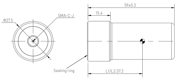
The position of the phase center differs for each model of GNSS antenna. The most frequently used GNSS antenna by TOPODRONE is the Harxon HX-CH6601A. The L1/L2 satellite signal frequency phase center of this GNSS antenna is located 37 mm from the bottom plane, exactly at the center. Thus, it is convenient to measure offsets to the base of the GNSS antenna mount.
If another model of GNSS antenna is used with the UAV alongside the TOPODRONE UAV PPK UPGRADE Kit, the height of the phase center must be verified in the manufacturer's technical documentation.
  |
  |
If another model of GNSS antenna is used with the UAV and the TOPODRONE UAV PPK UPGRADE Kit, the height of the phase center must be verified in the manufacturer's technical documentation.
No Comments