TOPODRONE 100/100+/200+
- Disclaimer
- TOPODRONE LiDAR design and overview
- Supply package
- Requirements and operating conditions
- Technical specifications
- Setting up the laser sensor
- TOPODRONE LiDAR to backpack installation
- TOPODRONE LiDAR to mobile mount installation
- Installing TOPODRONE LiDAR on DJI Matrice 300 / M350
- Switching on and initializing the TOPODRONE LiDAR
- Overlaps between scans and the height of the scanned objects
- IMU calibration pattern
- Airborne Laser Scanning (ALS)
- Mobile Laser Scanning (MLS)
- Downloading data from TOPODRONE LiDAR
- Ground Control Points (GCP) for TOPODRONE LiDAR
- Frequently Asked Questions
Disclaimer
TOPODRONE LiDAR 100/100+/200+ - are high-accuarate surveying measuring instruments that require careful and precise handling to ensure a long service life.
Do not use the TOPODRONE LiDAR in any way not described in this manual or the user's guide.
Do not subject TOPODRONE LiDAR to shock or vibration, especially when the unit is turned on.
Do not place TOPODRONE LiDAR in direct sunlight, in places with poor ventilation, or near a source of heat or cold.
Do not fully or partially submerge the laser scanner in water or expose the product to heavy rain, snow, sand, or dust for extended periods of time.
Do not insert foreign objects into the memory card, LEMO 6-Pin and external GNSS antenna slots, or install the memory card upside down or attempt to connect incompatible slots.
Do not insert or remove the MicroSD card while the TOPODRONE LiDAR is operating, as this may cause the card to malfunction and/or data loss.
Safe storage of TOPODRONE LiDAR.
When the TOPODRONE LiDAR is not in use, it is recommended to store the device in a room with a relative humidity of 40% or less and a temperature of 20±5°C.
If the TOPODRONE LiDAR gets wet from rain, snow or fog during operation, wipe it with a clean, dry paper or microfiber cloth. Then leave it in a dry room for an hour to dry completely.
Technological requirements
TOPODRONE LiDAR operate using PPK technology and require GNSS data for the duration of their operation from the base station for data post-processing.
To obtain correct data from TOPODRONE LiDAR it is necessary to have a quality GNSS signal during operation, both for the geodetic receiver and for the base station.
The manufacturer does not guarantee the performance of TOPODRONE LiDAR in case of intentional or accidental violation of any of the requirements described above.
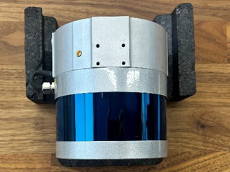
TOPODRONE LiDAR design and overview
TOPODRONE LiDAR 100/100+/200+ is a multifunctional device designed for airborne and mobile laser scanning (ALS and MLS) of the earth's surface. The main task of the TOPODRONE LiDAR is to acquire data to generate a dense cloud of terrain points, which in turn allows the classification and processing of this data. The obtained data can be used for various tasks such as geodesy, cartography, volume measurement, taxation and monitoring of various objects.
TOPODRONE LiDAR can operate in a variety of environments, including dense grass, forest or urban areas, under all lighting conditions. However, for effective operation of TOPODRONE LiDAR it is necessary to have sufficient Global Navigation Satellite Systems (GNSS) signal. The use of SLAM technology in the post-processing software TOPODRONE Post Processing allows you to get highly accurate data even in the presence of a weak GNSS signal on the main trajectory.
In the process, to obtain optimal results, the laser scanner should cover certain areas of the ground surface with at least 30% overlap (106 degrees under the UAV in VLS, and 360 degrees around in MLS).
Subsequently, the data from the laser scanner are processed sequentially in several software to equalize the data, align the scans, filter out noise, classify the point cloud, and produce the final materials:1
1. TOPODRONE Post Processing, which calculates a high-precision laser scanner trajectory, generates a dense raw point cloud and initially aligns the scans to each other (Strip Alignment).
2. LiDAR360 software, which performs high-precision alignment of scans to each other (Strip Alignment) and applies several filters to reduce noise and improve the accuracy of the final point cloud. LiDAR360 software can then classify the point cloud and generate final materials (DEM, DEM, etc.).
Further post-processing of data from TOPODRONE LiDAR is performed in the software that is necessary to fulfill the final tasks for a particular user.
Application of SLAM technology in TOPODRONE Post Processing software allows you to get highly accurate data even in the presence of weak GNSS signal on the main trajectory.
TOPODRONE PPK GNSS receiver integrated into TOPODRONE LiDAR, together with high-precision inertial measurement unit (IMU) allows to obtain high-precision coordinates of the TOPODRONE LiDAR trajectory after post-processing, as well as high-precision coordinates of photo centers from TOPODRONE P24 / P61 cameras, synchronizing both devices by cable. GNSS receiver records “raw” GNSS measurements in *.UBX format and time stamps of the TOPODRONE P24 / P61 camera shutter, if it is connected.
Operation of TOPODRONE LiDAR without GNSS signal is not possible.
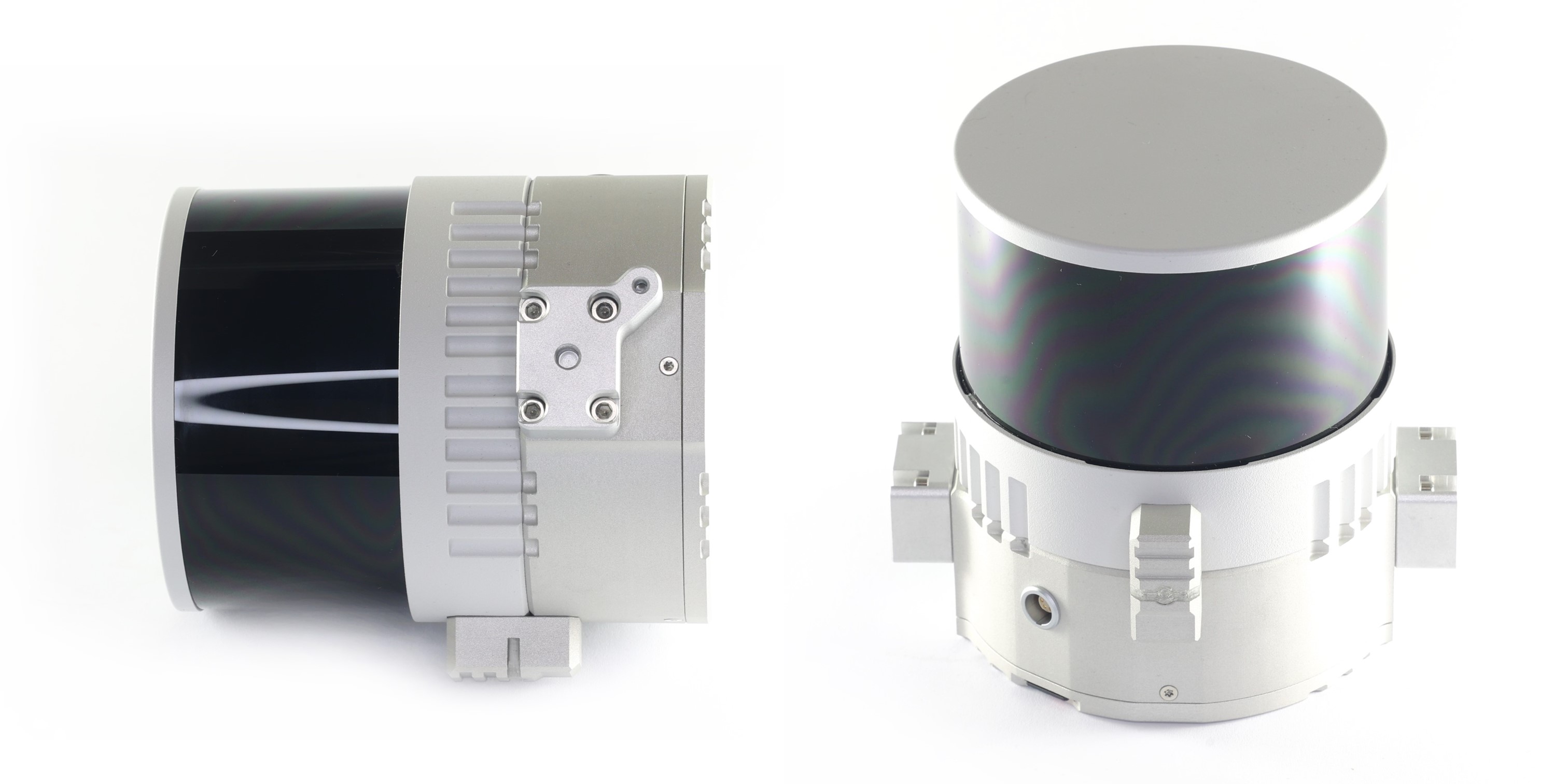
TOPODRONE LiDAR 100 / 100+ / 200+ is based on the following modules and systems:

-
LiDAR sensor housing;
-
Sensor lens;
-
Operation status LED;
-
TOPODRONE LiDAR housing;
-
Mounting holes with M3 thread;
-
High precision inertial measurement unit (IMU);
-
LEMO FFA.00 connector for external GNSS antenna cable connection;
-
USB Type-C 2.0 connector;
-
Mounting holes with M3 thread;
-
LEMO 6 pin connector;
-
Micro-SD memory card slot;
-
GNSS receiver TOPODRONE.
Description of TOPODRONE LiDAR 100 / 100+ / 200+ components:
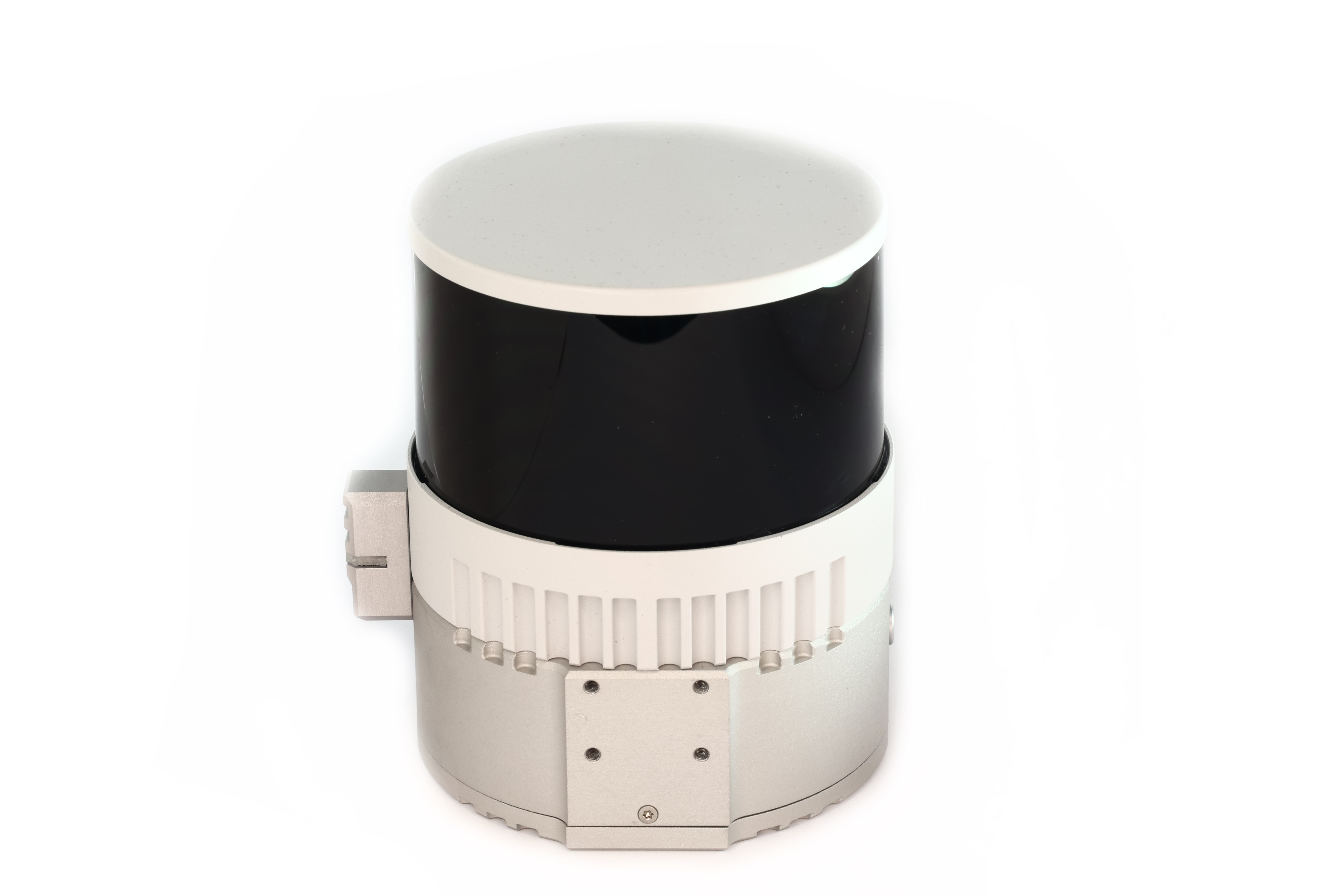
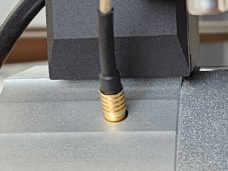
1. LiDAR Hesai sensor housing. Made of aluminium alloy, coated with grey enamel. During operation, the housing may slightly vibrate and make sounds and may heat up to 60°C. This effect is caused by the rotation of the scanning units of the laser heads inside the case, as well as heat dissipation from the working internal components.
2. LiDAR Hesai sensor lens. It is made of glass with polymer anti-reflective coating. It acts as a filter that transmits light only in the working wavelengths of the laser, as well as mechanical protection of the scanning rotating laser heads of the sensor. The coating of the laser scanning sensor lens is vulnerable to scratching and chipping. It is strongly recommended that the TOPODRONE LiDAR lens be treated with care and not be operated under conditions that could damage or scratch the surface of the laser scanning sensor. If scratches and damage occur, the quality of the acquired data may deteriorate. Individual single minor scratches do not generally reduce the quality of the data.
3. TOPODRONE LiDAR status LED. Displays the current operating status of the device. Below is the decoding of the light signals:
|
Switching on and off |
||
|
1 |
Infrequent green flashes | Charging Ionistors Normal ~10 seconds |
|
2 |
Flashing green |
Linux booting |
|
3 |
Flashing red, siren |
After 1 minute of flashing green |
|
4 |
Green |
Linux booted, waiting for services |
|
5 |
Rapid flashing green |
After power off, shutdown. Normal ~10 seconds |
|
Waiting for and recording data |
||
|
6 |
Green |
System initialisation |
|
7 |
Siren, flashing red |
Hardware problem with Ublox or IMU |
8 |
Green flashing orange |
Waiting for GNSS signal The better the signal, the faster the flicker |
|
9 |
Green |
Time setting Normally ~ 1 c |
|
10 |
Green flashing blue |
Start recording Normally ~ 10 s |
|
11 |
Triple signal, blue |
Recording |
|
Copying data (after connecting a USB stick) |
||
|
12 |
Green |
Recording stopped Normal ~ 1 c |
|
13 |
Flashing crimson, rising tone signal |
Start copying |
|
14 |
One flash red, siren |
Error mounting the USB stick Faulty USB stick or file system |
|
15 |
Two flashes red, siren |
Not enough space on the USB stick |
|
16 |
Flashing crimson |
Copying data Flickering speeds up during copying process |
|
17 |
Fast flashing red, siren |
Write error |
|
18 |
Green, decreasing tone signal |
All data copied |
4. TOPODRONE LiDAR housing. Made of aluminium alloy for better heat transfer and weight reduction. It is the main supporting structure of the LiDAR.
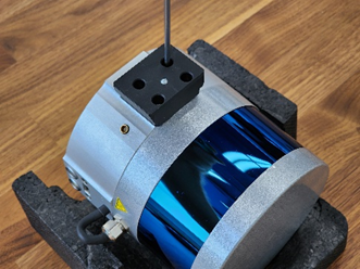
5. M3 fixing holes are made inside the aluminium body of TOPODRONE LiDAR for attaching it to a backpack or car mount.
6. The IMU (Inertial Measurement Unit), a high-precision inertial measurement unit, is used to record lateral and radial accelerations and inclination angles of the LiDAR during ALS and MLS operations. The data from the IMU is required for use in the post-processing phase for flight path equalisation. Antenna offsets are calculated from the centre of the IMU to the phase centre of the external GNSS antenna. Honeywell and Epson IMUs are used.
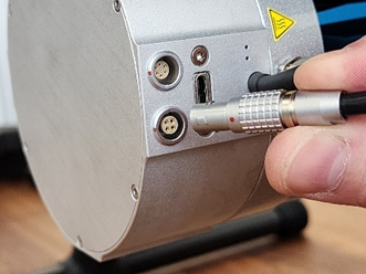
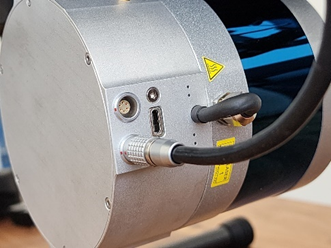
7. LEMO FFA.00 connector for connecting an external GNSS antenna. It is used for ALS and MLS. When performing ALS, it is necessary to connect the Helix cable of the antenna installed on the drone. When performing MLS it is necessary to connect the antenna cable from the GNSS antenna TOPODRONE BackPack.
8. USB Type-C Gen.3.2 connector is used to transfer data recorded in TOPODRONE LiDAR to an external storage device, as well as to connect to a mobile device via USB-OTG adapter to change the laser scanning angles and output the LiDAR Hesai sensor to the Internet when contacting the technical support service. Never connect external power to the USB Type-C connector.
9. M3 fixing holes for LiDAR attachment to the aircraft. The TOPODRONE quick-release mount is installed in these mounting holes.
10. LEMO 6-Pin connector to connect external power from a drone, backpack or mobile vehicle mount and get timestamps of the camera shutter.
11. Micro-SD memory card slot for data recording. If there is a memory card in this slot, formatted in NTFS format and there is enough free space on it, data is written directly to this memory card. If no memory card is installed, data is written to the internal flash memory. In this case, you will need to upload the data to an external storage device via the USB Type-C Gen.3.2 connector in the future
12. The TOPODRONE GNSS receiver is based on the uBlox chip. The data recording, storage and transmission system is based on a high-speed flash memory module with 256 GB capacity. The power system of TOPODRONE LiDAR is based on ionisers, which provide power to the electronic component to end the recording when the power supply is interrupted at the end of work.
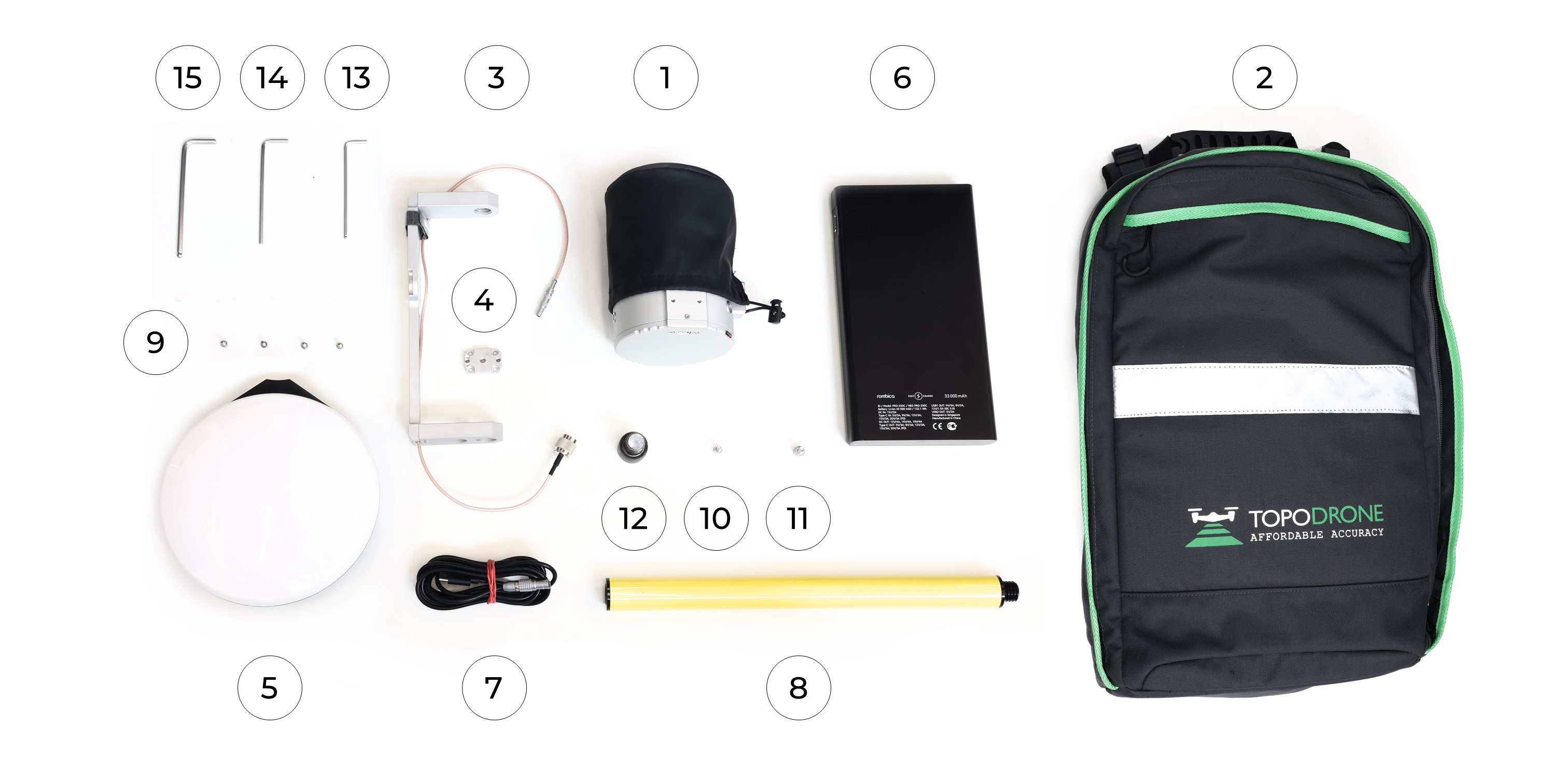
Supply package
| 1 | TOPODRONE LiDAR |
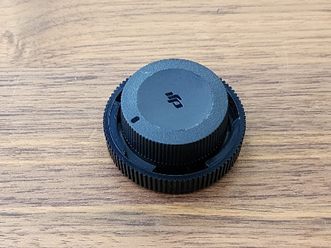
| 2 | Protective cover for the laser scanner lens |
| 3 | Quick-release dovetail mount - or mount the laser scanner to the UAV in the DJI SkyPort payload slot with protective cover - optional |
| 4 | Spare antenna cable with connectors |
| 5 | GNSS antenna mount with cable and mounting screws |
| 6 | External GNSS antenna |
| 7 | MicroSD card at least 32 GB |
| 8 | External USB Type-C flash drive not less than 32 GB |
| 9 | OTG USB Type-C to USB Type-A adapter |
| 10 | Cloth for wiping the lens |
| 11 | Power supply 220V (USB Type-C) for power supply (PD 12-15-20V) |
| 12 | USB-Type-C to LEMO 6-PIN power cable for power supply power supply |
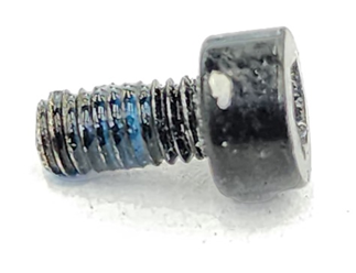
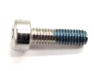
| 13 | M3x8 screws for attaching TOPODRONE LiDAR to the mount with DJI SkyPort connector |
| 14 | Protective carrying case with a lodgement for transportation |
Requirements and operating conditions
TOPODRONE LiDAR are designed for use in weather without precipitation. Operation in rain, snow, frost, hail and fog is prohibited. The construction of TOPODRONE LiDAR does not have protection according to IP standard and in case of violation of this recommendation, moisture can get on the surface of the scanning lens and inside the device. This, in its turn, may deteriorate the quality of the received data, as well as damage the internal structure of the laser scanner itself. If precipitation begins, we recommend that you stop using the equipment. If scanning is performed in the presence of even slight rain, additional noise from false reflections due to water droplets or snow may occur.
 |
| Noises from false reflections of the TOPODRONE LiDAR, ALS was conducted during rain. |
Operation of the TOPODRONE LiDAR in sub-zero temperatures and high humidity (above 80%) can lead to icing of the equipment and the drone. This can deteriorate the quality of the acquired data, as well as cause damage to the laser scanner structure and even lead to the aircraft crashing during ALS due to icing of the carrying propellers and their probable firing as a result of a sharp increase in the mass of the carrying blades.
 |
 |
| DJI M200 and TOPODRONE LIDAR icing | DJI M200 blades and icing |
When operating TOPODRONE ALS laser scanners in winds above 7 m/s, it is necessary to increase the side overlap of the drone between scans, as the wind can affect the number of overlapping areas. Operation of TOPODRONE LiDAR for MLS in strong winds is limited by the physical capabilities of the operator. The maximum recommended wind strength when performing ALS is 10 m/s. High winds have a much lower impact on data quality degradation when performing MLS than when performing ALS. It is not recommended to perform terrain surface scanning immediately after rain or wet snow, when there is still a thin film of water on the surface due to much worse reflection and, as a consequence, less number of points received from the surface.
For correct data post-processing it is necessary to perform at least two passes in forward and reverse directions with overlap of at least 30% relative to each other. A single pass is not effective. In case of insufficient quality or complete absence of GNSS signal, operation of TOPODRONE 100/100+/200+ laser scanners is impossible. The minimum visible number of satellites is 8 (above the elevation mask of 15°). It is strongly recommended to check the weather conditions and the number of visible GNSS satellites before the flight. It does not always make sense to perform ALS / MLS in the same area at different times.
Operation of the TOPODRONE LiDAR requires careful and gentle handling of the main lens of the laser scanning sensor. This lens has a surface hardness similar to plastic, not glass. Due to this fact, foreign objects can easily scratch the surface of the sensor. Minor single scratches on the sensor will not result in a noticeable deterioration of the data quality. To protect the lens surface from scratches, it is recommended to use a cover. It is not recommended to keep the TOPODRONE LiDAR switched on for more than 4 hours.
The manufacturer is not responsible for equipment malfunction or for obtaining poor or inaccurate data when used outside the recommended operating conditions.
Technical specifications
| 200+ | 100+ | 100 | |
| Sensor Type: | XT32M2X | XT32 | XT16 |
| Laser Sensor Drive Type: | Mechanical circular rotation | Mechanical circular rotation | Mechanical circular rotation |
| Max. range of beam (m): | 300 | 120 | 120 |
| XYZ accuracy (cm): | 3-5 | 3-5 | 3-5 |
| Max. sensor rpm: | 1200 | 1200 | 1200 |
| Recommended rsensor pm: | 600 | 600 | 600 |
| Number of laser beams (pcs): | 32 | 32 | 16 |
| MLS all-round viewing angle: | 0-360 | 0-360 | 0-360 |
| ALS Angle of circular view: | 217-323 | 217-323 | 217-323 |
| Vertical viewing angle: | 40.3(+19.5…-20.8) | 31(+15…-16) | 30(+15…-15) |
| Horizontal resolution, °: | 0.09 | 0.09 | 0.09 |
| Vertical resolution, °: | 1.3 | 1 | 2 |
| Weight (g): | 800 | 1000 | 1000 |
| Dimensions (WxDxH) (mm): | 118х155х105 | 120х155х105 | 120х155х105 |
| Laser operating wavelength (nm): | 905nm | 905nm | 905nm |
| Reflection type: | Triple Return | Dual Return | Dual Return |
| Number of points at single reflection | 640000 | 640000 | 320000 |
| Number of dots for double reflection | 1280000 | 1280000 | 640000 |
| Number of dots at triple reflection | 1920000 | - | - |
| Laser Safety Class: | Class 1 safe for eyes | Class 1 safe for eyes | Class 1 safe for eyes |
| Power consumption (watt.): | 10 | 10 | 9 |
| Operating voltage, V | 12–28 | 12–28 | 12–28 |
| Connectors for power supply: | LEMO 4 PIN, USB-Type-C | LEMO 4 PIN, USB-Type-C | LEMO 4 PIN, USB-Type-C |
| Antenna connector: | LEMO FFA.00 | LEMO FFA.00 | LEMO FFA.00 |
| Min. number of visible satellites to pass initialisation: | 8 | 8 | 8 |
| Max. ALS wind strength (m/s): | 10 | 10 | 10 |
| Operating temperature range: | -20°C ... +60°C | -20°C ... +60°C | -20°C ... +60°C |
| Storage temperature range: | -40°C ... +60°C | -40°C ... +60°C | -40°C ... +60°C |
| Operating humidity range: | 20% ... 95% | 20% ... 95% | 20% ... 95% |
| IMU operating frequency (Hz): | 200 | 200 | 200 |
| Recommended operating altitude (m): | 70-150 | 90-110 | 90-110 |
| Supported GNSS systems and frequencies: |
GPS: L1C/A, L2C; GLONASS: L1OF, L2OF; GALILEO: E1B/C, E5b; BEIDOU: B1I, B2I |
GPS: L1C/A, L2C; GLONASS: L1OF, L2OF; GALILEO: E1B/C, E5b; BEIDOU: B1I, B2I |
GPS: L1C/A, L2C; GLONASS: L1OF, L2OF; GALILEO: E1B/C, E5b; BEIDOU: B1I, B2I |
| Number of GNSS receiver channels: | 184 | 184 | 184 |
| Raw measurement recording frequency, Hertz: | 10 | 10 | 10 |
| Yaw axis accuracy (°, 1σ): | 0.08 | 0.08 | 0.08 |
| Pitch axis accuracy (°, 1σ): | 0.03 | 0.03 | 0.03 |
| Roll axis accuracy (°, 1σ): | 0.03 | 0.03 | 0.03 |
| Memory cards supported | MicroSD | MicroSD | MicroSD |
| Memory card file system | exFAT | exFAT | exFAT |
| Internal memory capacity (Gb): | 256 | 256 | 256 |
| External media connection type: | USB Type-C | USB Type-C | USB Type-C |
| Country of manufacture: | Switzerland | Switzerland | Switzerland |
| Possible installation options | Aircraft, car, backpack | Aircraft, car, backpack | Aircraft, car, backpack |
Setting up the laser sensor
When using TOPODRONE LiDAR for ALS, the laser sensor Field-of-view angles are limited to 106 degrees due to the design feature of the applied drones (chassis). At the same time, the full view of the laser sensor (360 degrees) should be used to perform MLS. To change the angle of view of the TOPODRONE LiDAR it is necessary to perform the procedure of connecting the TOPODRONE LiDAR to the Internet using a cell phone and the web-interface of the laser sensor with local connection via Wi-Fi.
The following components and conditions are required to perform the TOPODRONE laser sensor working angle adjustment procedure:
- Mobile Android device (smartphone or tablet) (Only Samsung, Honor, Xiaomi phones are tested, other manufacturers' mobile devices may not work correctly) with 3G/4G/5G mobile Internet or Wi-Fi network with Internet connection;
- USB Type-C OTG adapter (supplied with the package);
- USB cable for connection to a mobile device (supplied with the smartphone/tablet);
- TOPODRONE LiDAR;
- Power supply (supplied with the kit) or power from the aircraft via a cable with LEMO 6 pin connector or power cable from Li-Po battery (supplied with the mobile kit);
- Computer or other mobile device with any internet connection.
To connect to the web interface of the TOPODRONE LiDAR via a local network, the following steps must be performed strictly in the following order:
- Make sure that the TOPODRONE LiDAR is securely located on the back cover on a flat, stable horizontal surface or attached to the aircraft / mobile vehicle mount on a standard mount. Due to the gyroscopic torque, the TOPODRONE LiDAR may start to move if it is not securely positioned and fall down after it is turned on. Never place the TOPODRONE LiDAR on an uneven, slippery surface or on its side with the lens touching the surface.
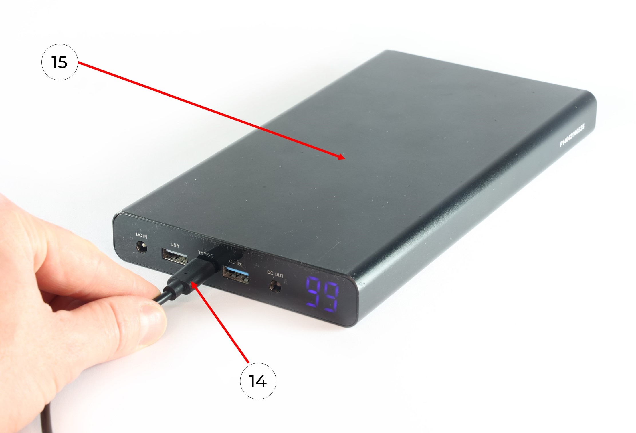
- Power up the TOPODRONE LiDAR by connecting it to a power supply unit or aircraft or to a external PowerBank. To power the TOPODRONE LiDAR from the PowerBank, it must be turned on with a short press of a button on a PowerBank.
- Wait for the TOPODRONE LiDAR to turn on and boot up (once the TOPODRONE LiDAR has finished booting up, the LED should be solid green and the yellow LED should turn off).
- Using a computer or mobile device, go to the available Wi-Fi networks section and find the network with the name TOPODRONE_LIDAR
- Connect to this network using the password topodrone.
- Then on your computer or other mobile device, open your browser and click on the link: http://192.168.10.1:10977/
- In the web interface that opens, find the line with the values Azimuth FOV Start XXX / End YYY, where XXX – is the angle in degrees of the beginning of the scan are, YYY – angle in degrees of the end of the scanning area.
- For ALS set the FOV Start: 217 End: 323. With this values the field of view (FOV) will be 106 degrees to the bottom of TOPODRONE LiDAR (53 degrees to the left and right of the nadir). After entering the desired values, click the Save button.
- For MLS, set the FOV Start: 000 End: 359. With this values the field of view (FOV) will be 360 degrees. After entering the desired values, click the Save button.
- Make sure that all other settings except the recording start and end angles match those in the screenshots below:

Setting the Laser Scanning Sensor Parameters for the ALS

Setting the Laser Scanning Sensor Parameters for the MLS
- The TOPODRONE LiDAR settings are now complete. Turn off the power to the laser scanner, disconnect all cables and put the equipment in the case if necessary.
To connect to the web interface of the TOPODRONE LiDAR via the Internet, the following steps must be performed strictly in the following order:
- Make sure that the TOPODRONE LiDAR is securely located on the back cover on a flat, stable horizontal surface or attached to the aircraft / mobile vehicle mount on a standard mount. Due to the gyroscopic torque, the scanner may start to move if it is not securely positioned and fall down after it is turned on. Never place the TOPODRONE LiDAR on an uneven, slippery surface or on its side with the lens touching the surface.
- Power up the TOPODRONE LiDAR by connecting it to a power supply unit or aircraft or to a external PowerBank. To power the TOPODRONE LiDAR from the PowerBank, it must be turned on with a short press of a button on a PowerBank.
- Wait for the TOPODRONE LiDAR to turn on and boot up (once the scanner has finished booting up, the LED should be solid green and the yellow LED should turn off).
- Connect the USB Type-C OTG adapter and USB cable to connect to your mobile device together via the USB Type-A connector (rectangular connector).
- Connect the USB Type-C OTG adapter to the TOPODRONE LiDAR's USB Type-C connector.
- Connect the USB cable for mobile device connection to a mobile device (smartphone or tablet) running Android OS
- Make sure your mobile device has an active Internet connection via 3G/4G/5G or Wi-Fi.
- In your mobile device, go to the menu: settings / connections / mobile hotspot and modem / USB modem mode pr Tethering mode (may differs in different languages).
- Then, on your computer or other mobile device, open your browser and click on the following link: http://node.gnss.cloud:10977/
- In the web interface that opens, find the line with the values Azimuth FOV Start XXX / End YYY, where XXX – is the angle in degrees of the beginning of the scan are, YYY – angle in degrees of the end of the scanning area.
- For ALS set the FOV Start: 217 End: 323. With this values the field of view (FOV) will be 106 degrees to the bottom of TOPODRONE LiDAR (53 degrees to the left and right of the nadir). After entering the desired values, click the Save button.
- For MLS, set the FOV Start: 000 End: 359. With this values the field of view (FOV) will be 360 degrees. After entering the desired values, click the Save button.
- Make sure that all other settings except the recording start and end angles match those in the screenshots below:
Setting the Laser Scanning Sensor Parameters for the ALS
Setting the Laser Scanning Sensor Parameters for the MLS
- The TOPODRONE LiDAR settings are now complete. Turn off the power to the TOPODRONE LiDAR, disconnect all cables and put the equipment in the case if necessary.
The procedure for connecting the TOPODRONE LiDAR to the Internet (steps 1-8) can also be used by TOPODRONE Technical Support for remote diagnostics.
The TOPODRONE LiDAR settings are saved until the next time you change them. It is strongly recommended to memorize or make a note of the currently set laser sensor angles. In case of incorrect initial settings, e.g. setting the ALS at the time of performing an MLS, the data from the excluded angles is not saved and cannot be retrieved in any way. On the contrary, if the TOPODRONE LiDAR is set to 360 degrees when performing ALS, the data will be more than 3 times redundant.
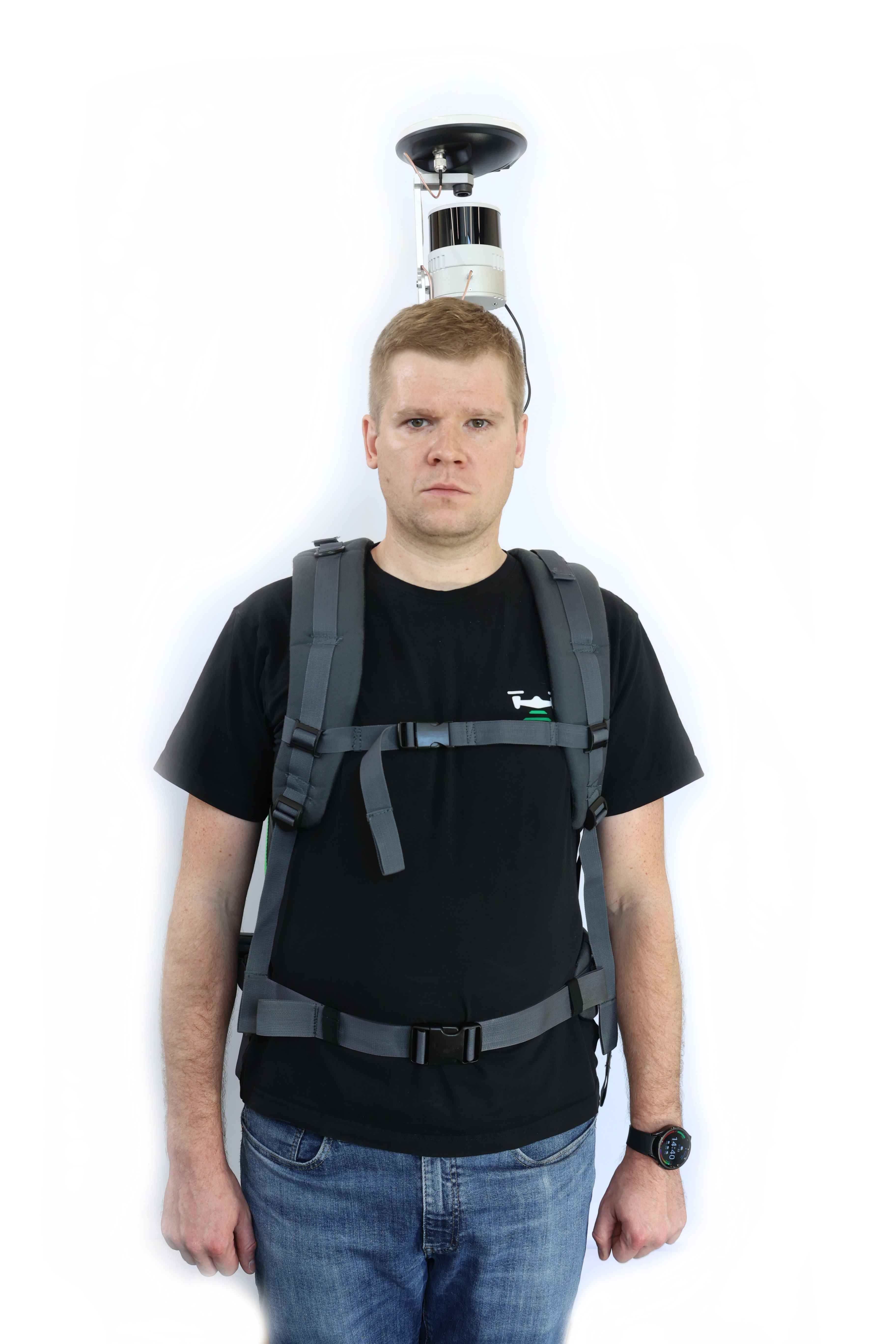
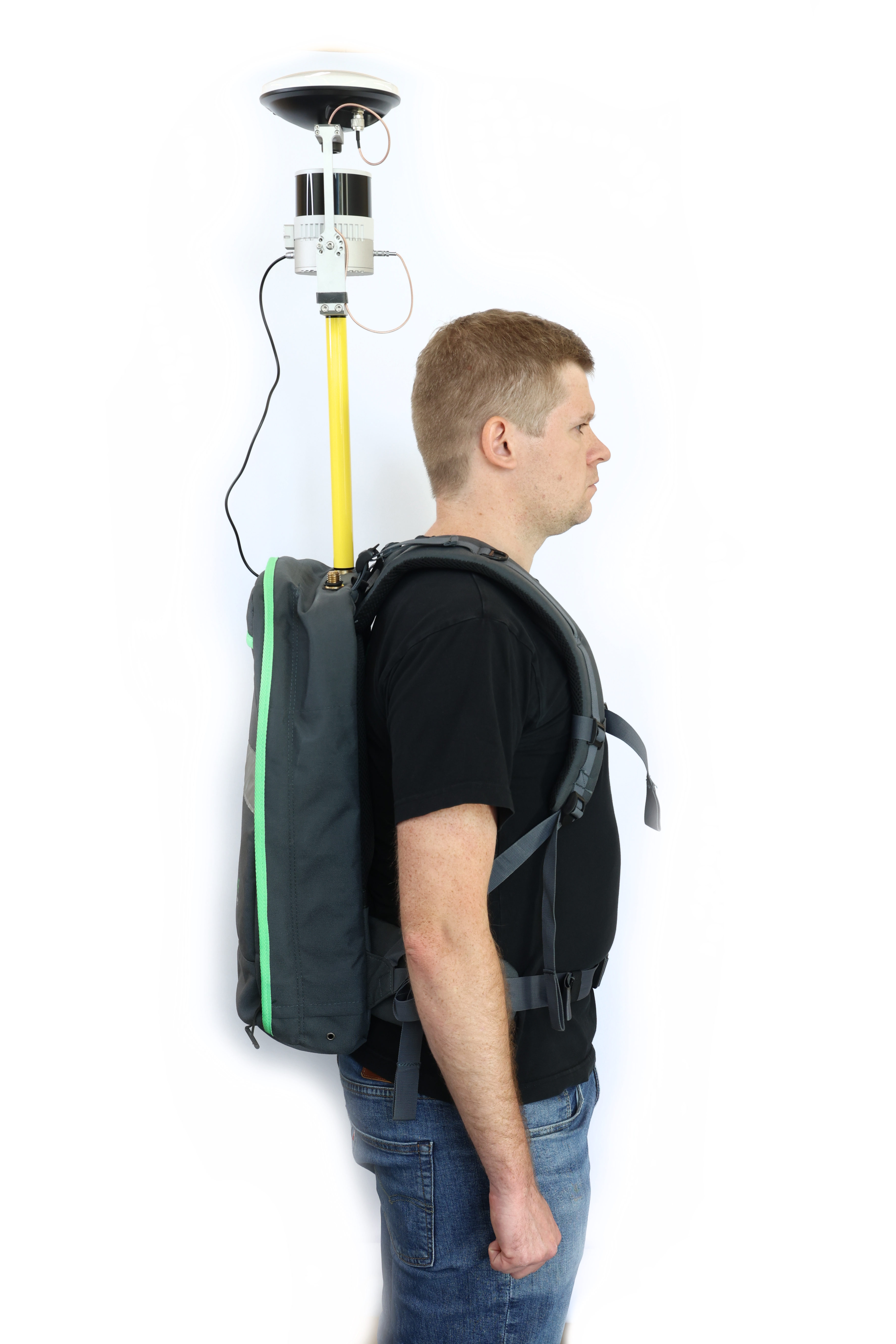
TOPODRONE LiDAR to backpack installation
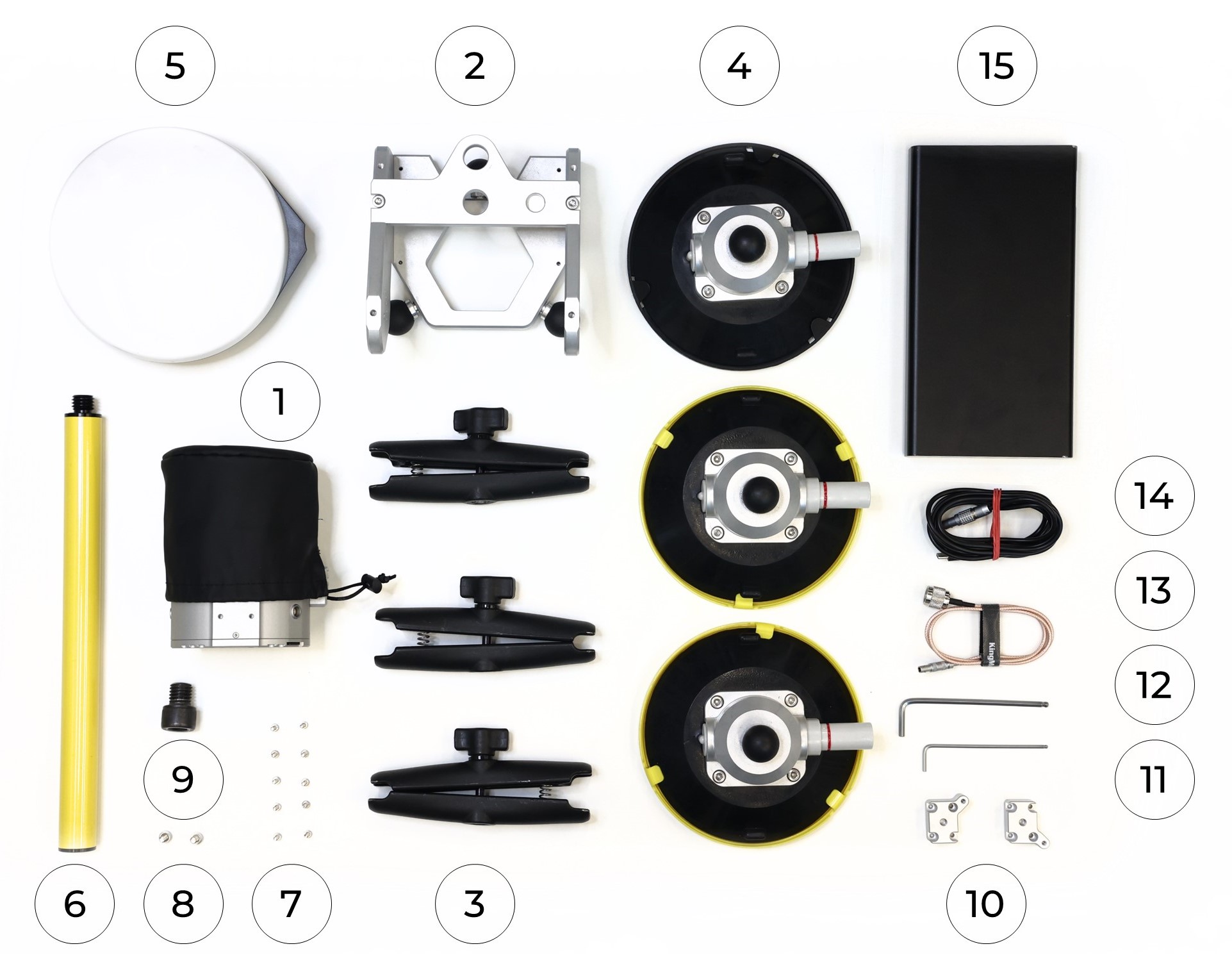
To install the TOPODRONE LiDAR on the backpack, you need the following components included in the package:
|
1. TOPODRONE LiDAR - 1 pc. 2. TOPODRONE Backpack - 1 pc. 3. Backpack LiDAR mount with antenna cable - 1 pc. 4. LiDAR mount spacer - 1 pc. 5. GNSS Antenna - 1 pc. 6. Power Bank - 1 pc. 7. LEMO 6 PIN - USB Type-C power cable - 1 pc. 8. Pole (30 cm) - 1 pc. |
9. Screw M3x8 - 4 pc. 10. Screw М4х8 - 1 pc. 11. Screw М5х8 - 1 pc. 12. Screw 5/8" - 11 UNC x 3/4" - 1 pc. 13. Hex 2.5 screwdriver - 1 pc. 14. Hex 3 screwdriver - 1 pc. 15. Hex 4 screwdriver - 1 pc. |
It is strongly recommended to use a protective soft cover for the TOPODRONE LiDAR to avoid the risk of damaging the laser scanning lens! For better clarity, in the photos shown, the TOPODRONE LiDAR is shown without the case.
To install the TOPODRONE LiDAR on the backpack, follow the steps below:
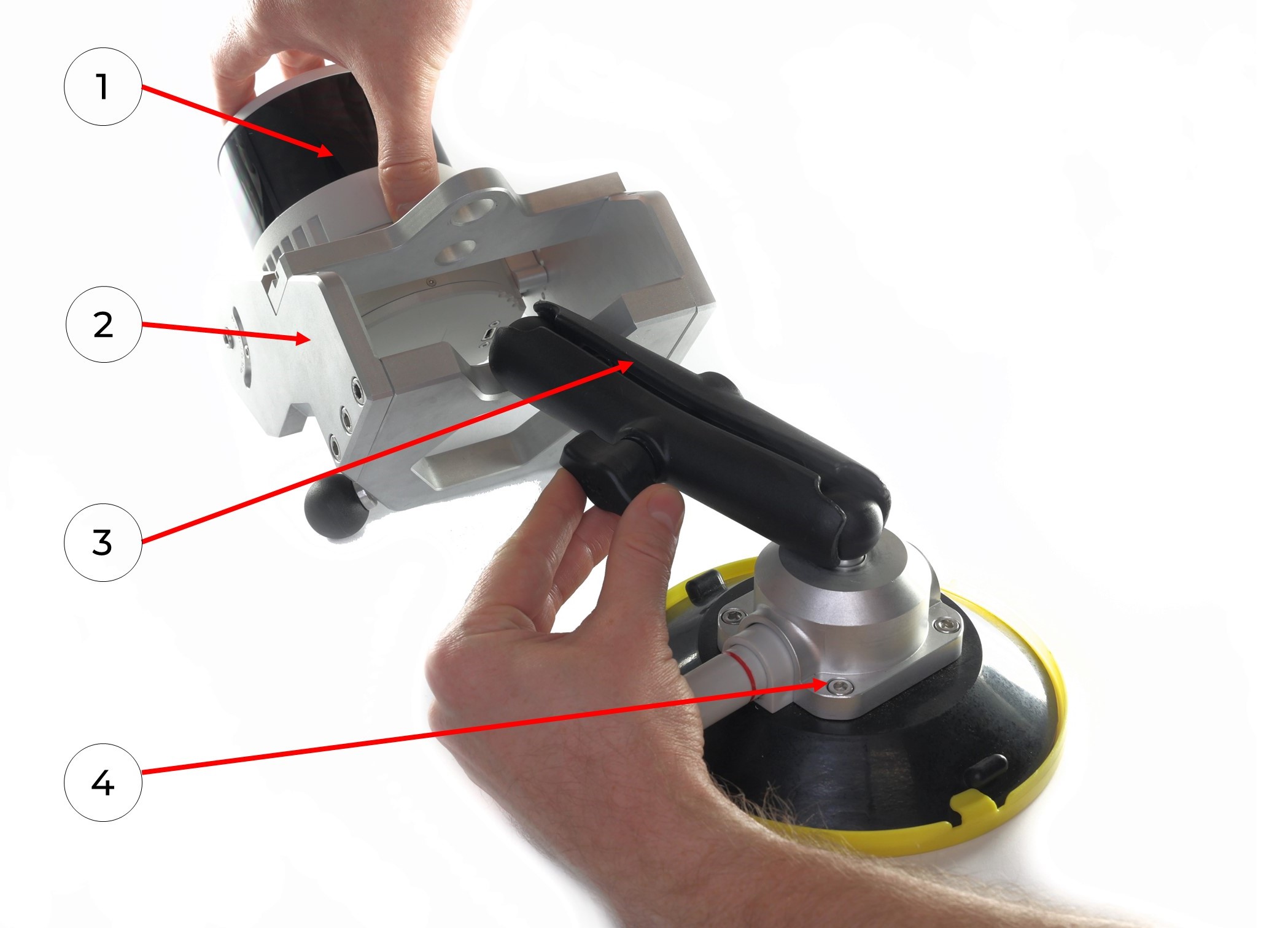
1. Place the TOPODRONE LiDAR (1) on a flat surface as shown in the photo.
2. Using a Hex M2.5 screwdriver (13) and M3x8 screws (9), install the laser scanner mount adapter (4) as shown in the photo.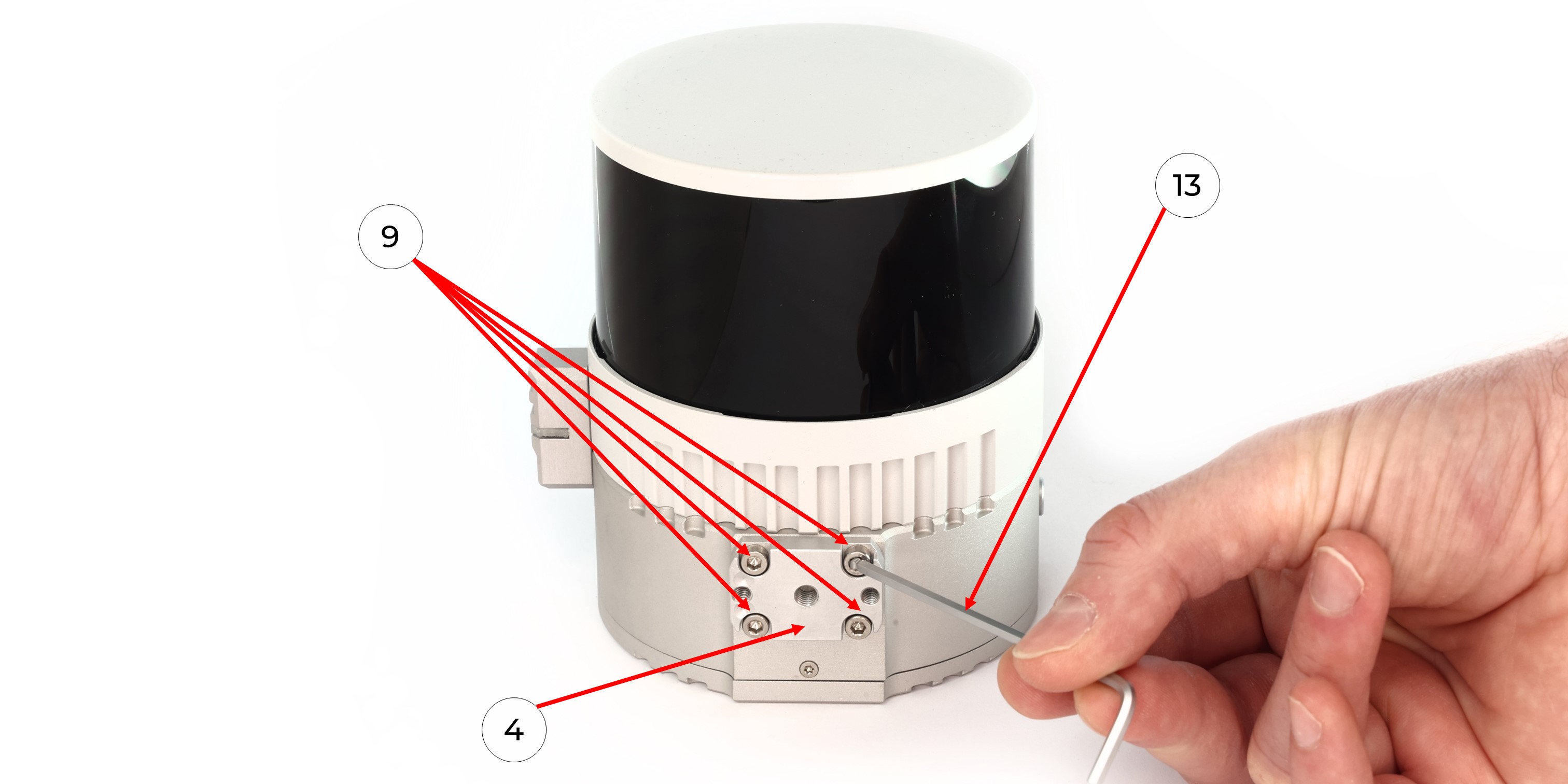 3. Manually screw the GNSS antenna (5) onto the Backpack Mount with antenna cable (3) using a 5/8“ - 11 UNC x 3/4” screw (12) as shown in the photo.
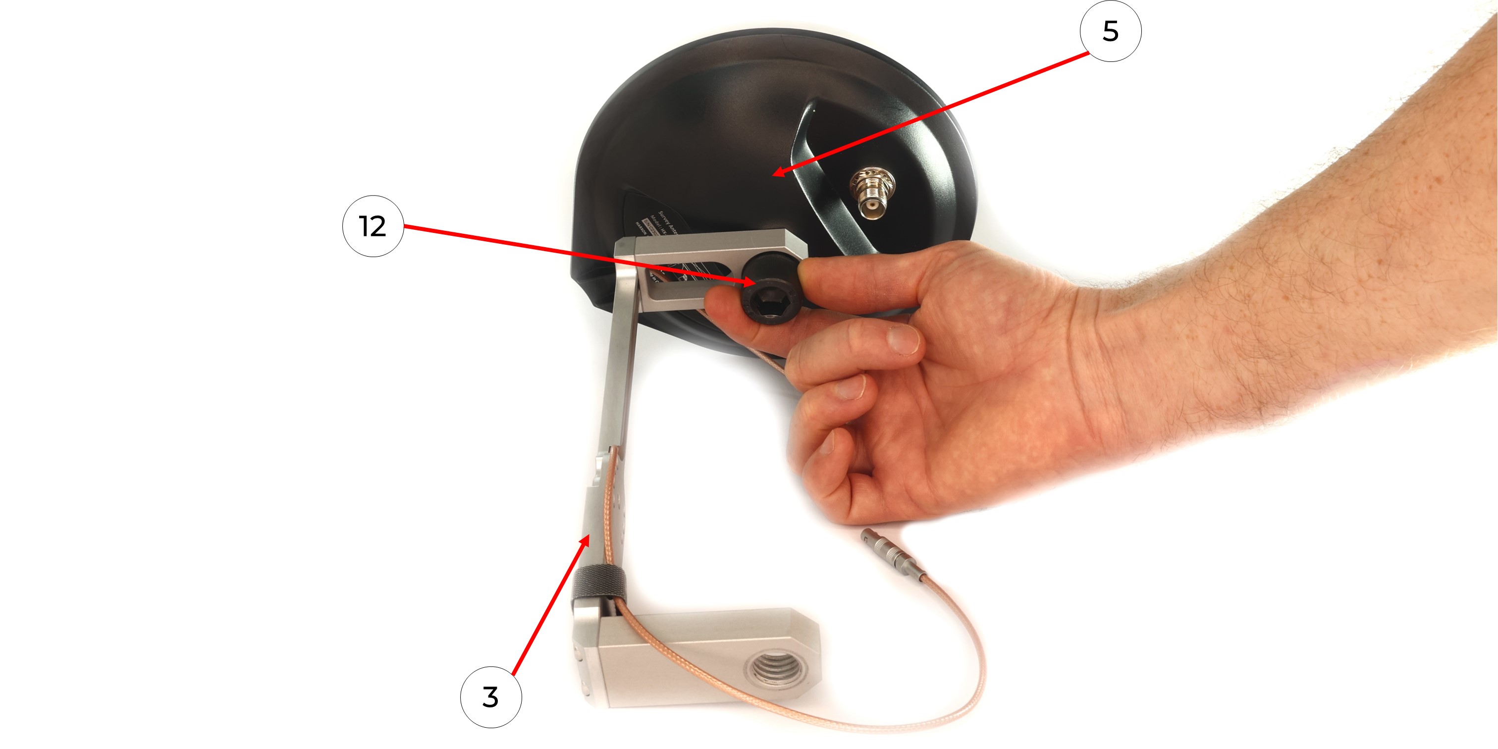
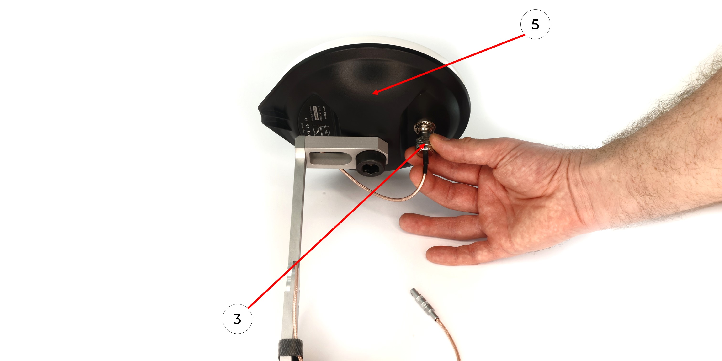
4. Connect the antenna cable (3) to the GNSS antenna (5), avoiding bends as shown in the photo.
5. Using a Hex 4 screwdriver (15) and an M5x8 screw (11), mount the TOPODRONE LiDAR to the fastening part of the backpack (3) without pinching the antenna cable.
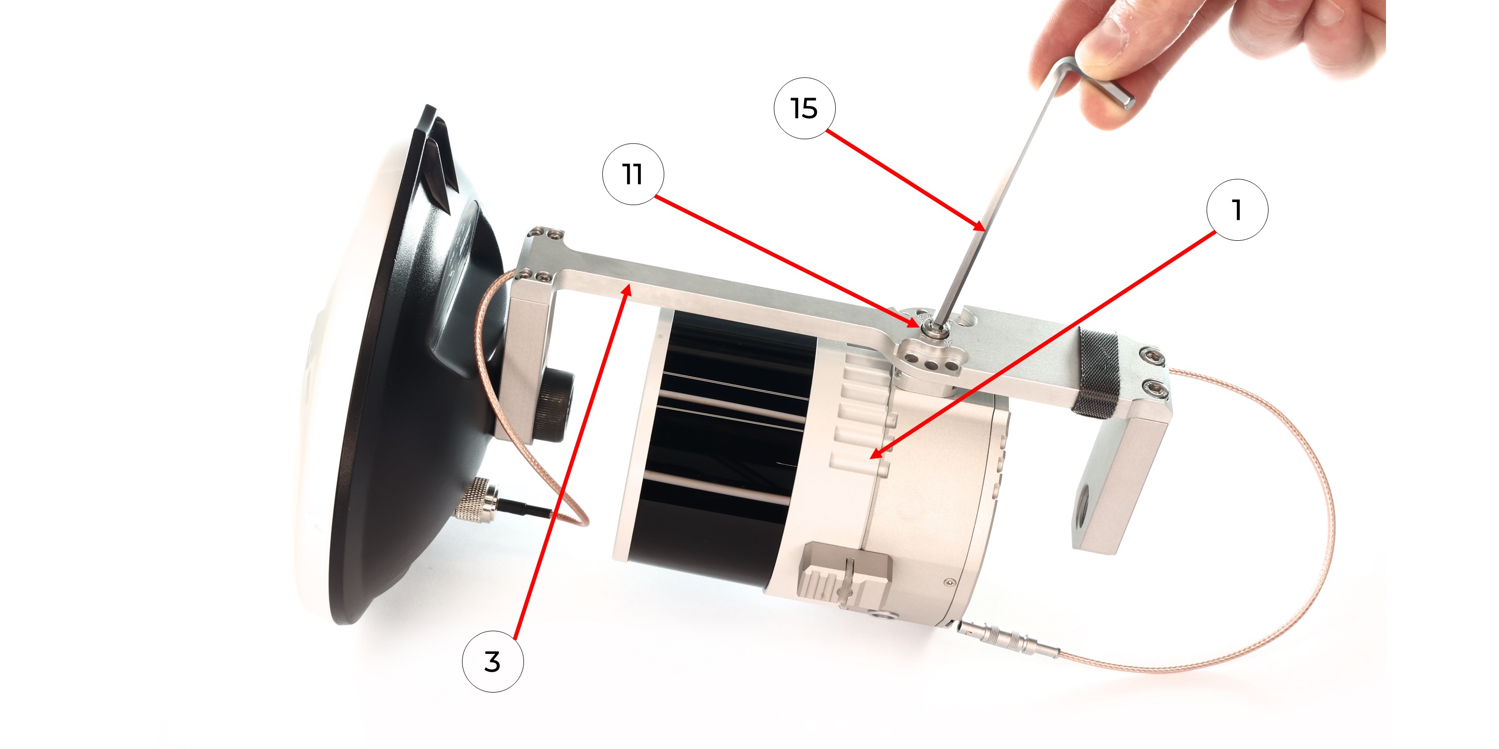
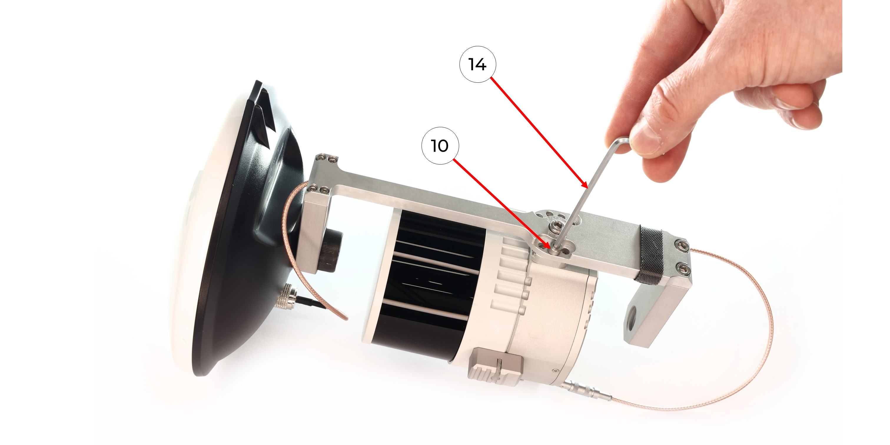
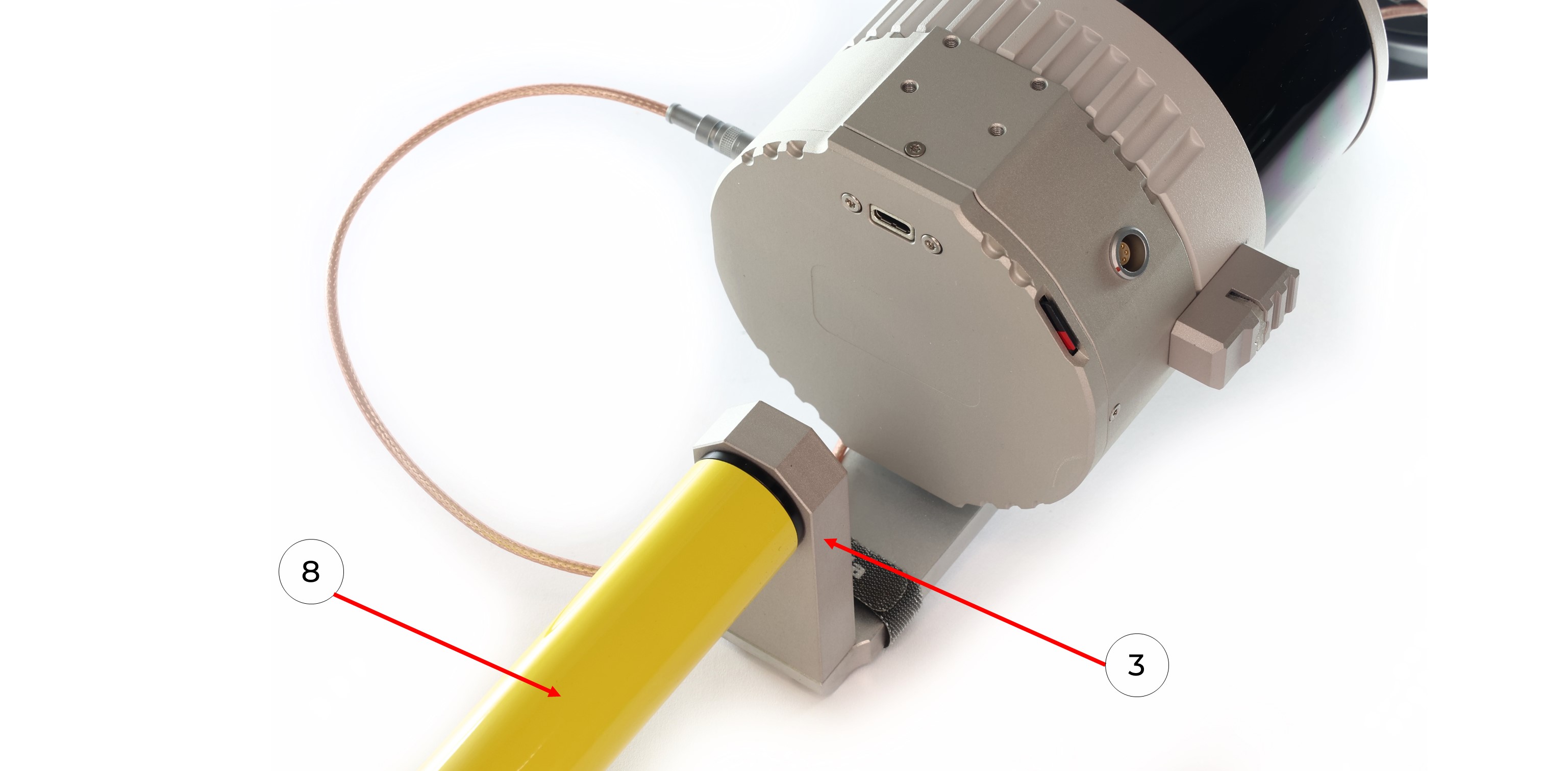
6. Position the TOPODRONE LiDAR on the mount at the required angle and fix it with the M4x8 screw (10) using a Hex 3 screwdriver (14).
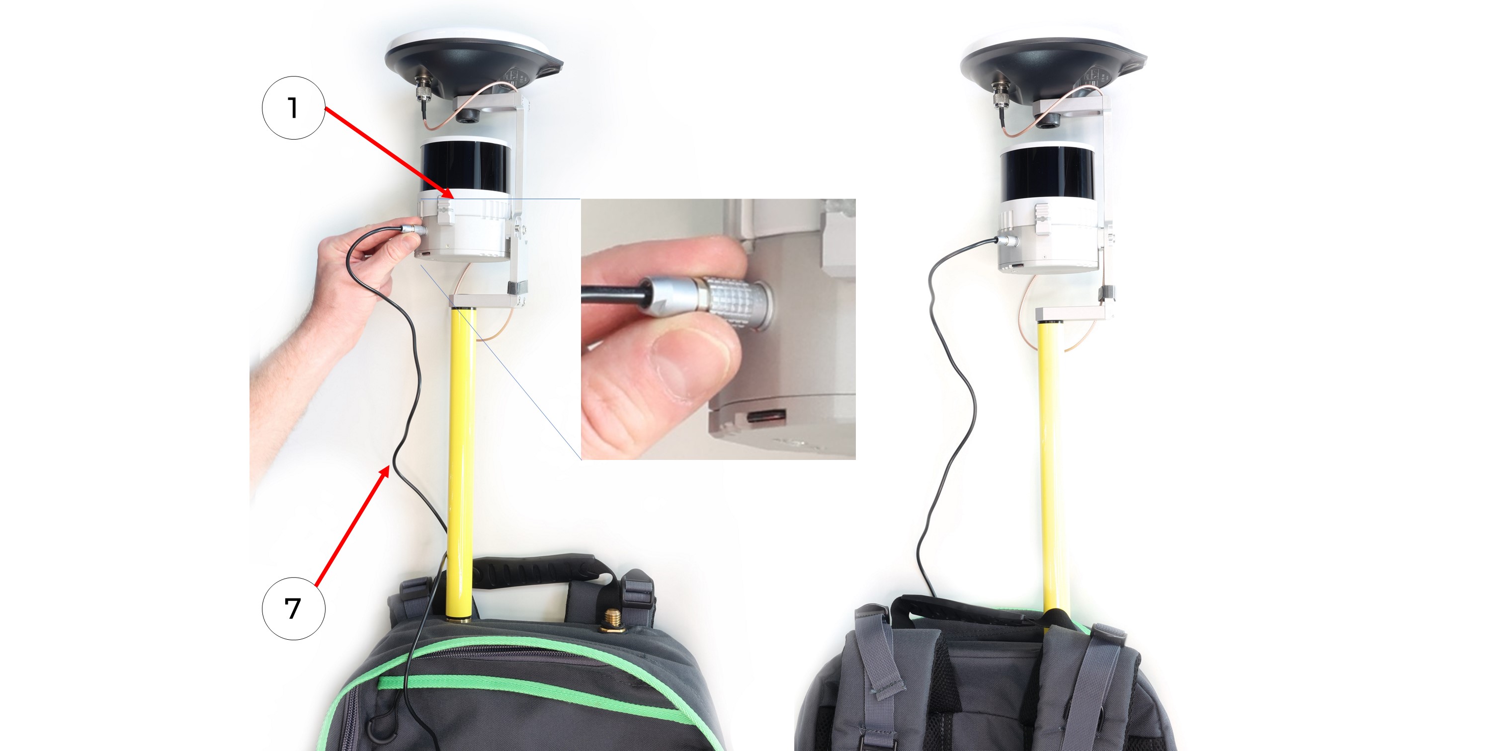
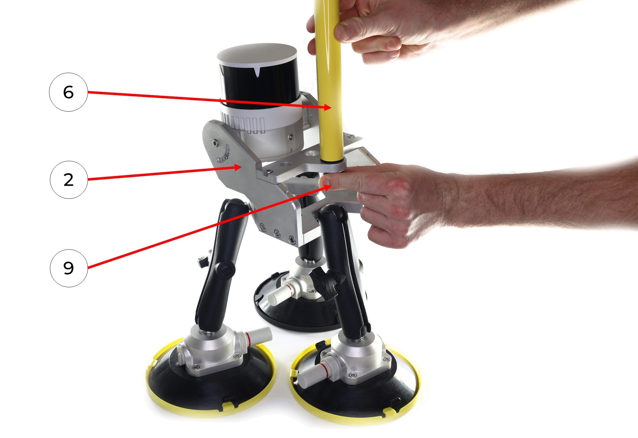
7. Connect the antenna connector of the LEMO mount (3) to the TOPODRONE LiDAR (1)
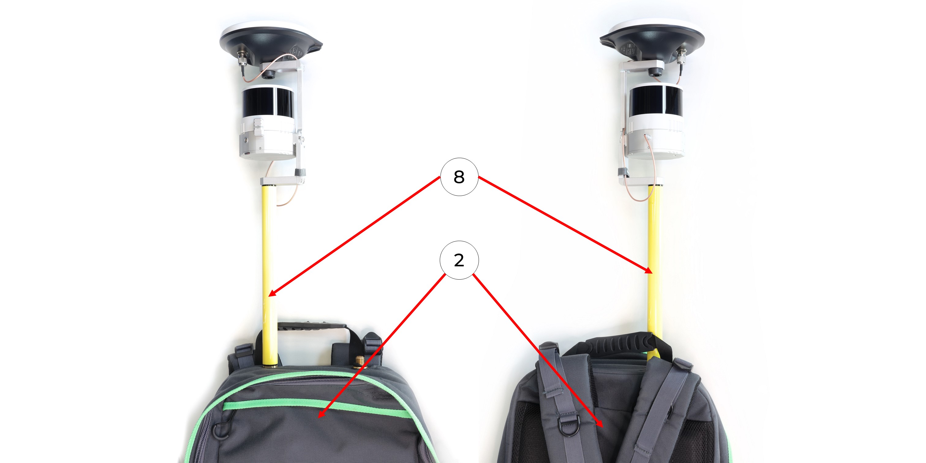
8. Screw the pole (8) to the backpack attachment (3).
9. Screw the pole (8) to the backpack (2) as shown in the photo. The LED of the TOPODRONE LiDAR should be positioned backwards.
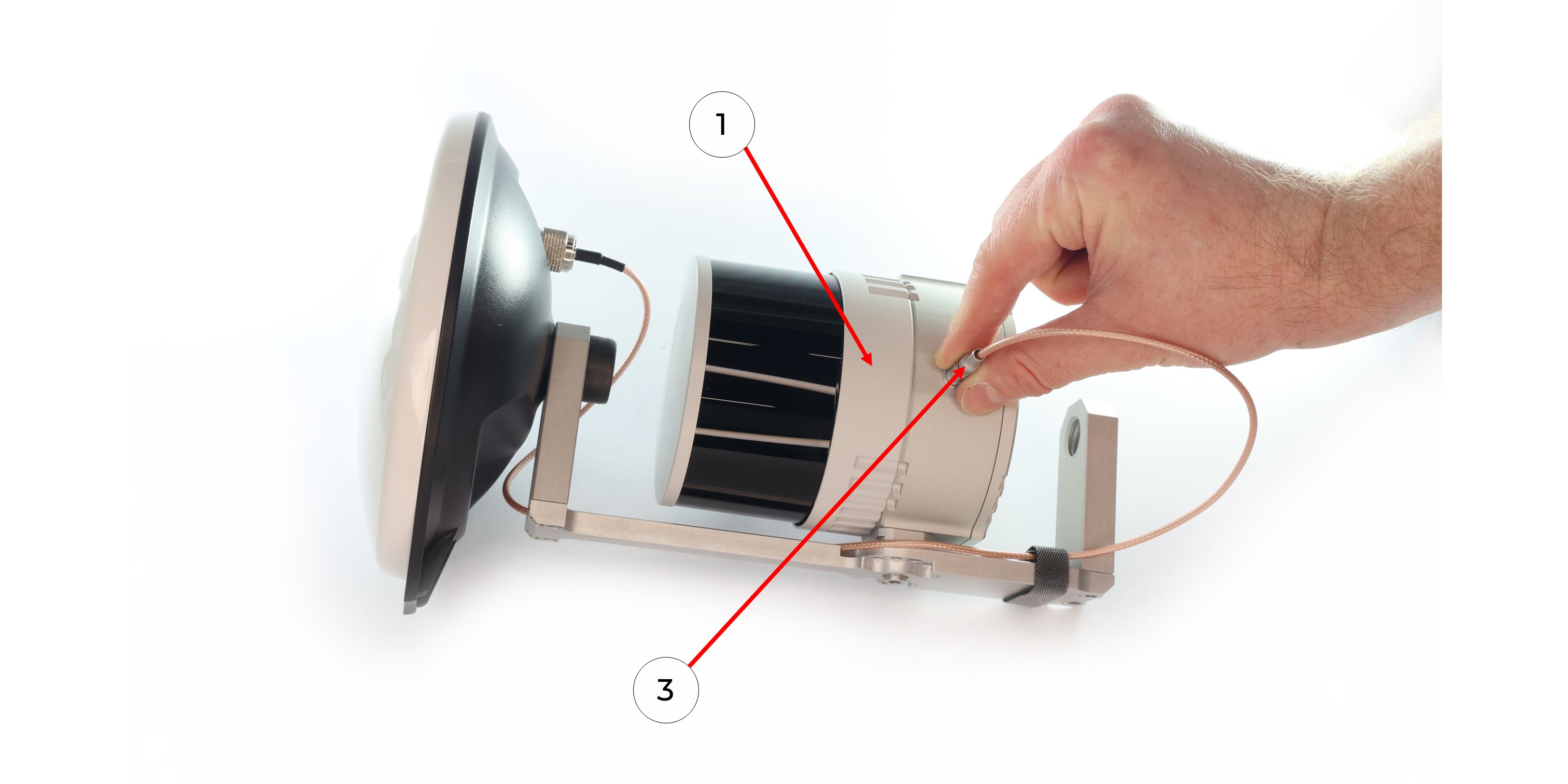
10. Connect the LEMO 6 PIN to USB Type-C power cable (7) to the TOPODRONE LiDAR (1).
11. Connect the LEMO 6 PIN to USB Type-C power cable (7) to the Power Bank (6) and apply power.
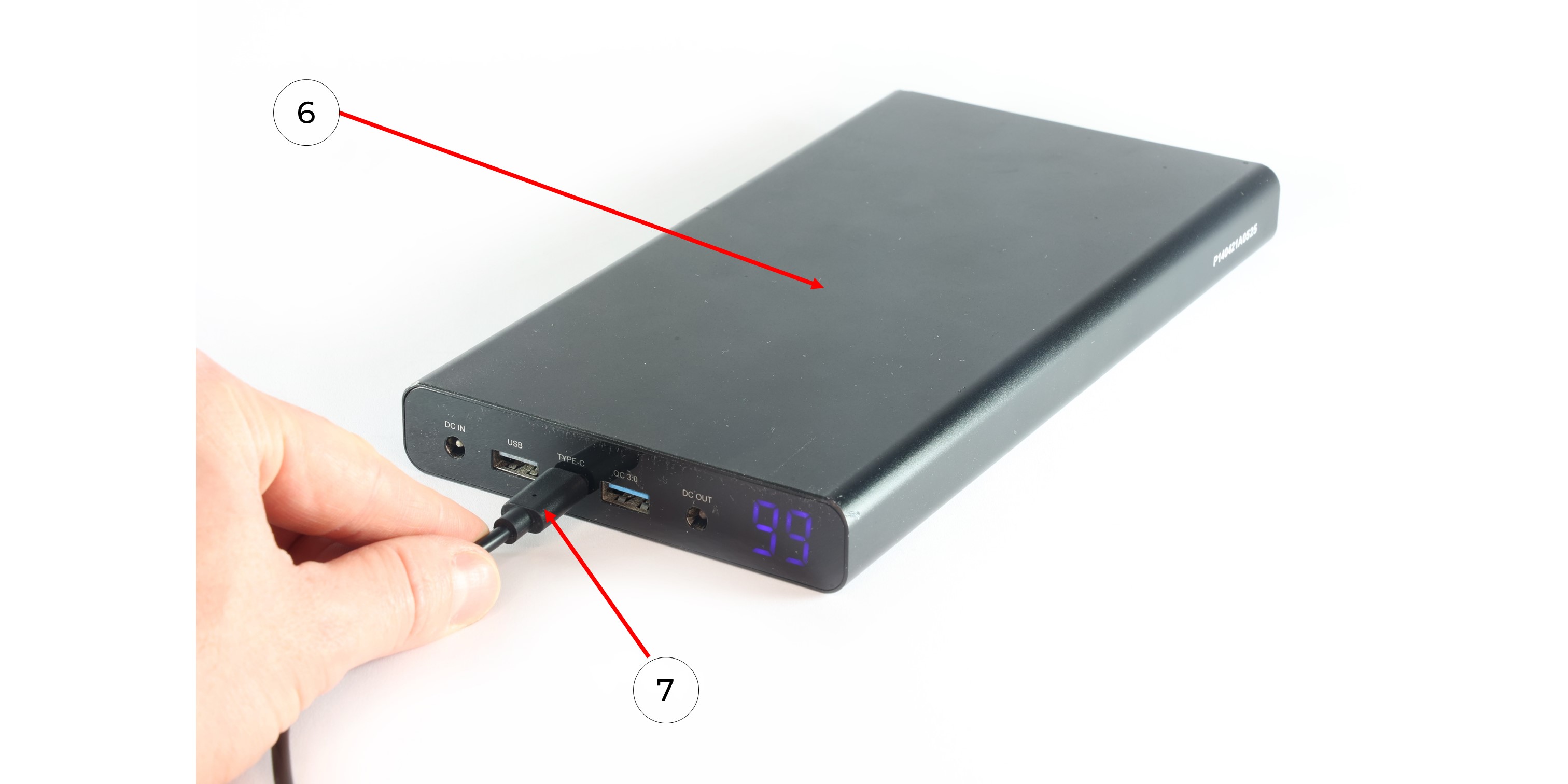
12. Put the Power Bank (6) into the backpack pocket (2) and wait for the TOPODRONE LiDAR (1) to turn on and initialize. Next - put on the backpack as shown in the photo and start the MLS.
|
|
|
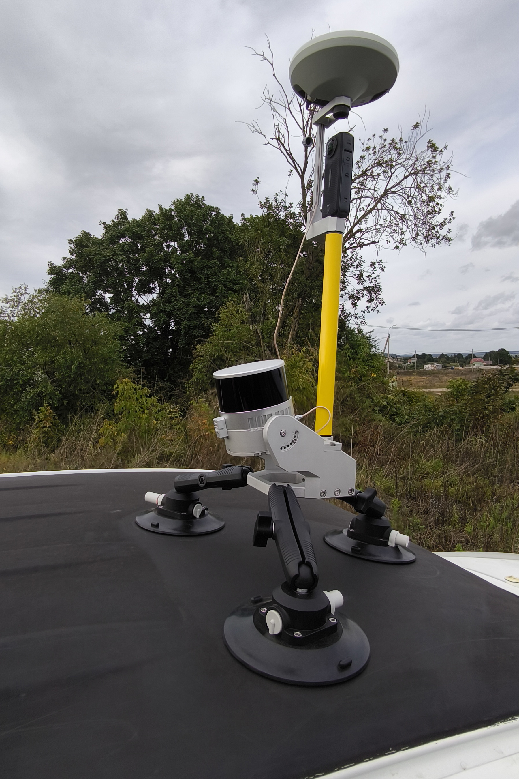
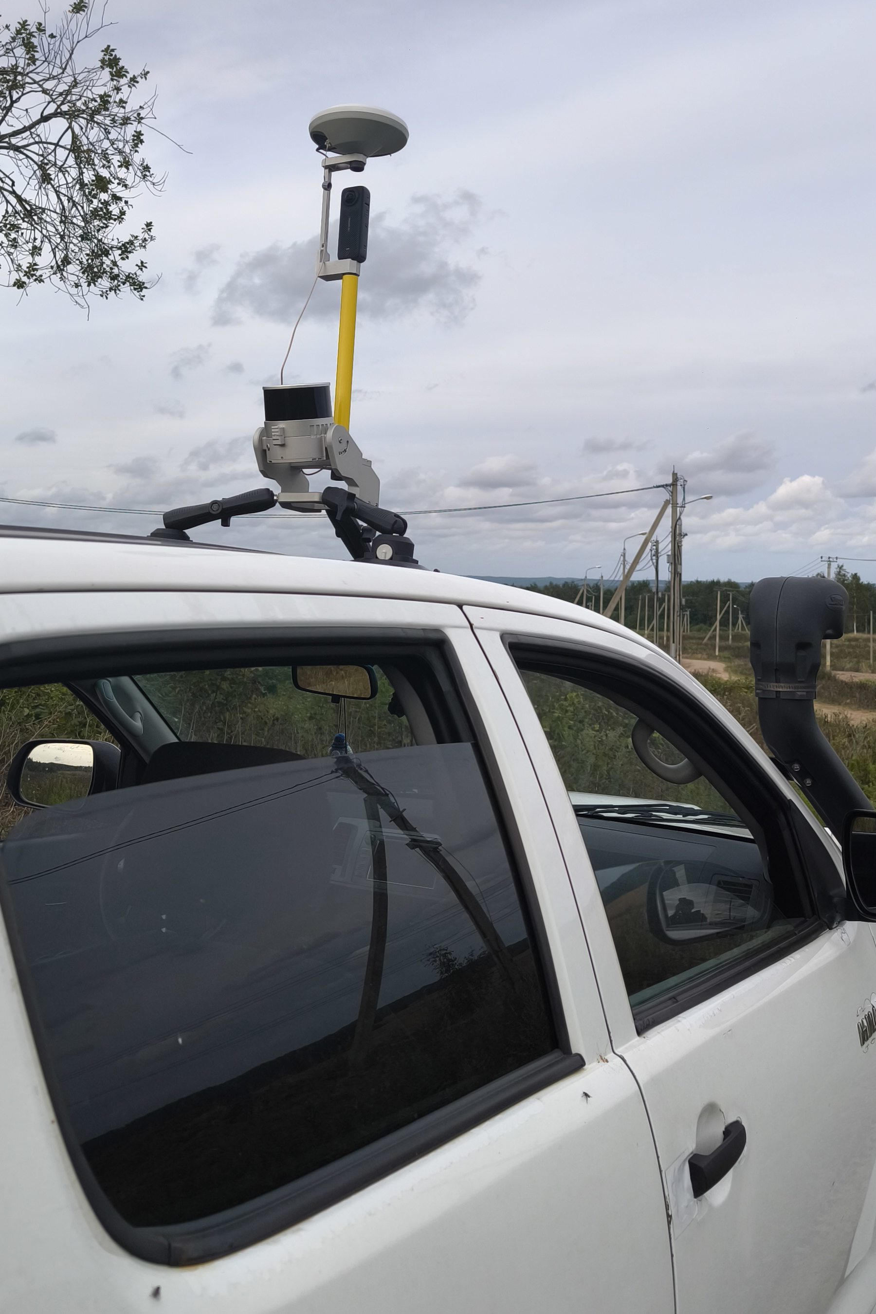
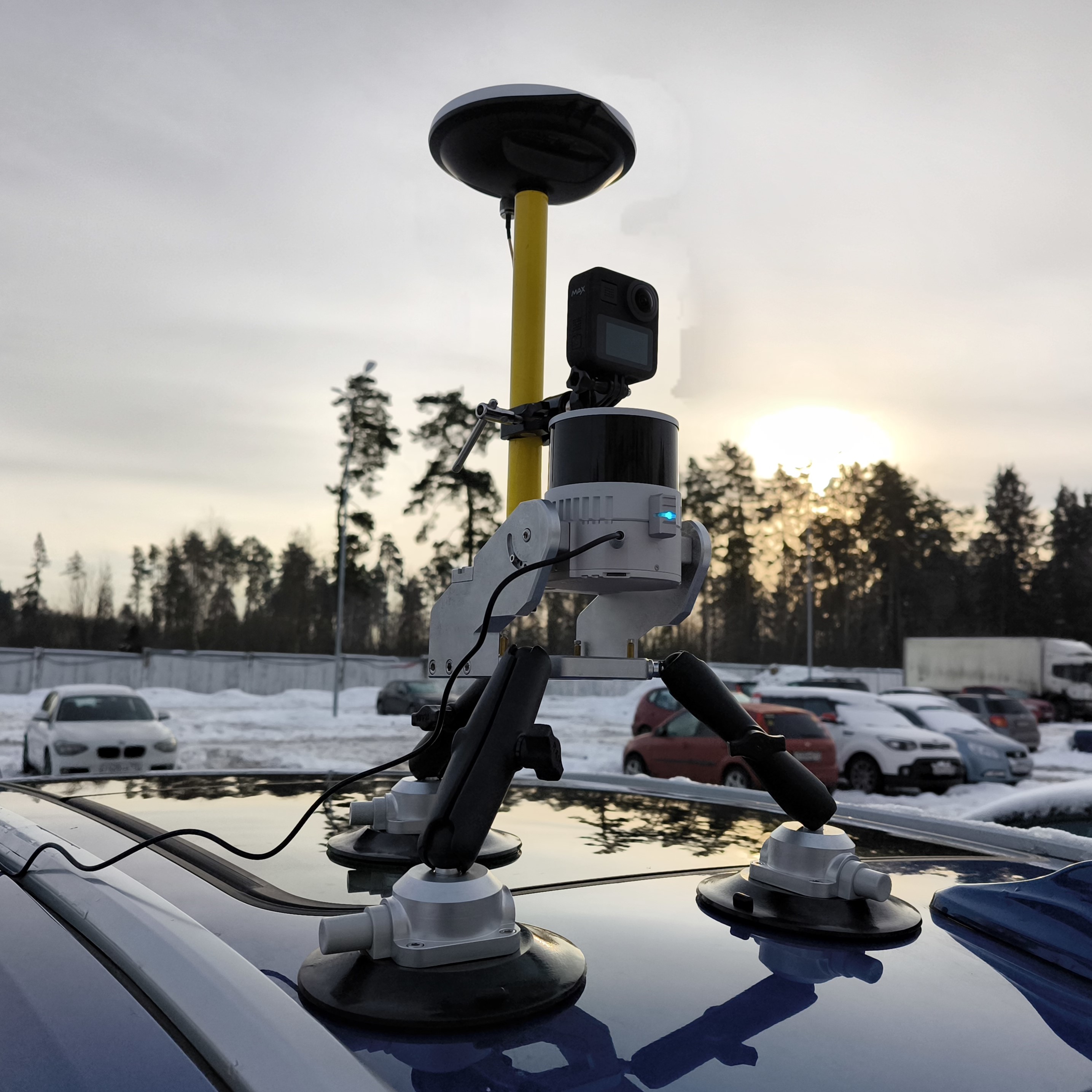
TOPODRONE LiDAR to mobile mount installation
To install the TOPODRONE LiDAR on the mobile mount, you will need the following components included in the kit:
|
1. TOPODRONE LiDAR - 1 pc. 2. Mobile mount base - 1 pc.. 3. Mobile mount arm - 3 pc. 4. Mobile mount suction cup - 3 pc. 5. GNSS antenna - 1 pc. 6. Pole (30 cm) - 1 pc. 7. M3x10 screw - 10 pc. 8. М5х10 screw - 2 pc. |
9. 5/8" - 11 UNC x 3/4" screw - 1 pc. 10. Mobile mount spacer - 2 pc. 11. Hex 2.5 screwdriver - 1 pc. 12. Hex 4 screwdriver - 1 pc. 13. Antenna cable - 1 pc. 14. LEMO 6 PIN - USB Type-C power cable - 1 pc. 15. Power Bank - 1 pc. |
It is strongly recommended to use a TOPODRONE LiDAR protective soft cover for to avoid the risk of damaging the laser scanning lens! For better clarity, in the photos shown, the TOPODRONE TOPODRONE LiDAR is shown without the case.
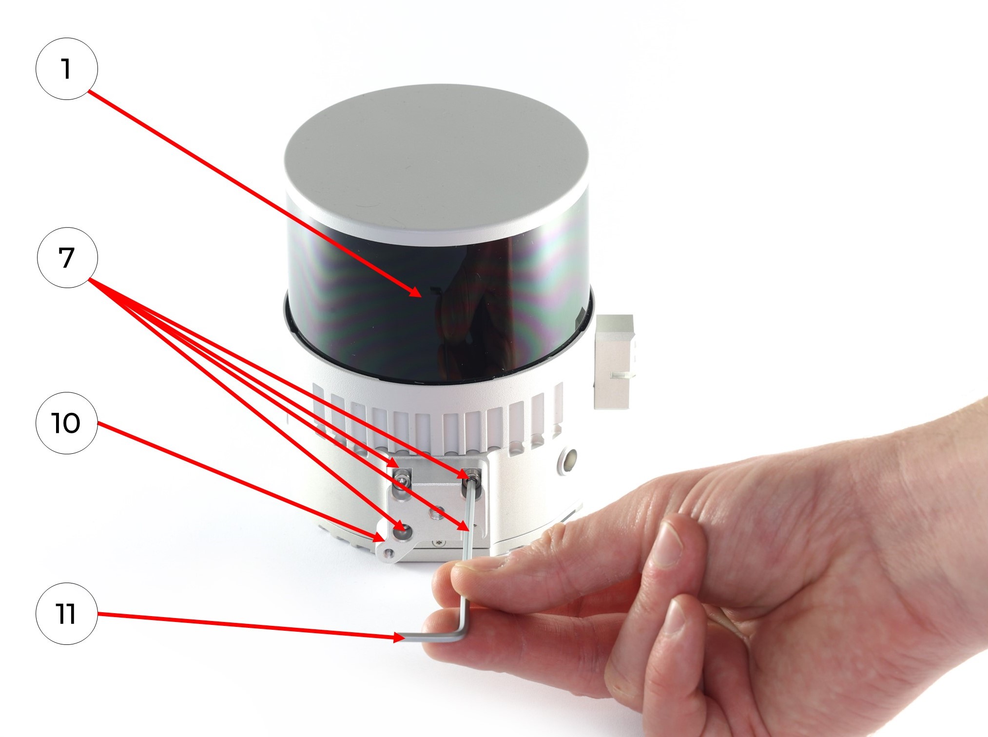
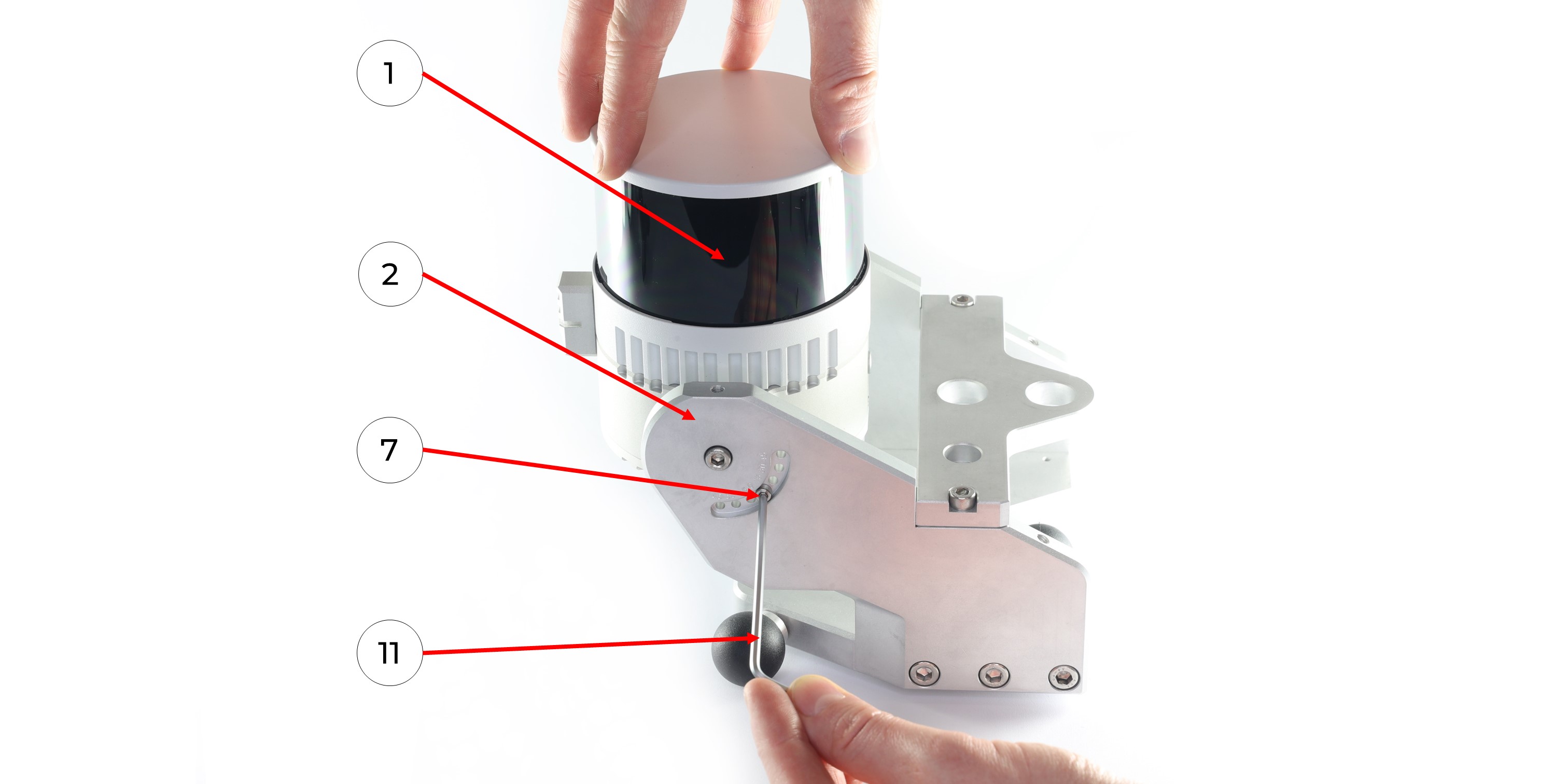
1. Install the two mobile mount spacers (10) on the TOPODRONE LiDAR (1) with 8 M3x10 (7) screws using a Hex 2.5 (11) screwdriver as shown in the photo:
|
|
|
2. Install TOPODRONE LiDAR (1) on the mobile mount base (2) with two M5x10 screws (8) using a Hex 4 (11) screwdriver as it shown at the photo below. Be extremely careful at this step!
Hold the TOPODRONE LiDAR (1) so that it does not fall and proceed to step 3. Use the cover to protect the lens! It is especially important in this step!
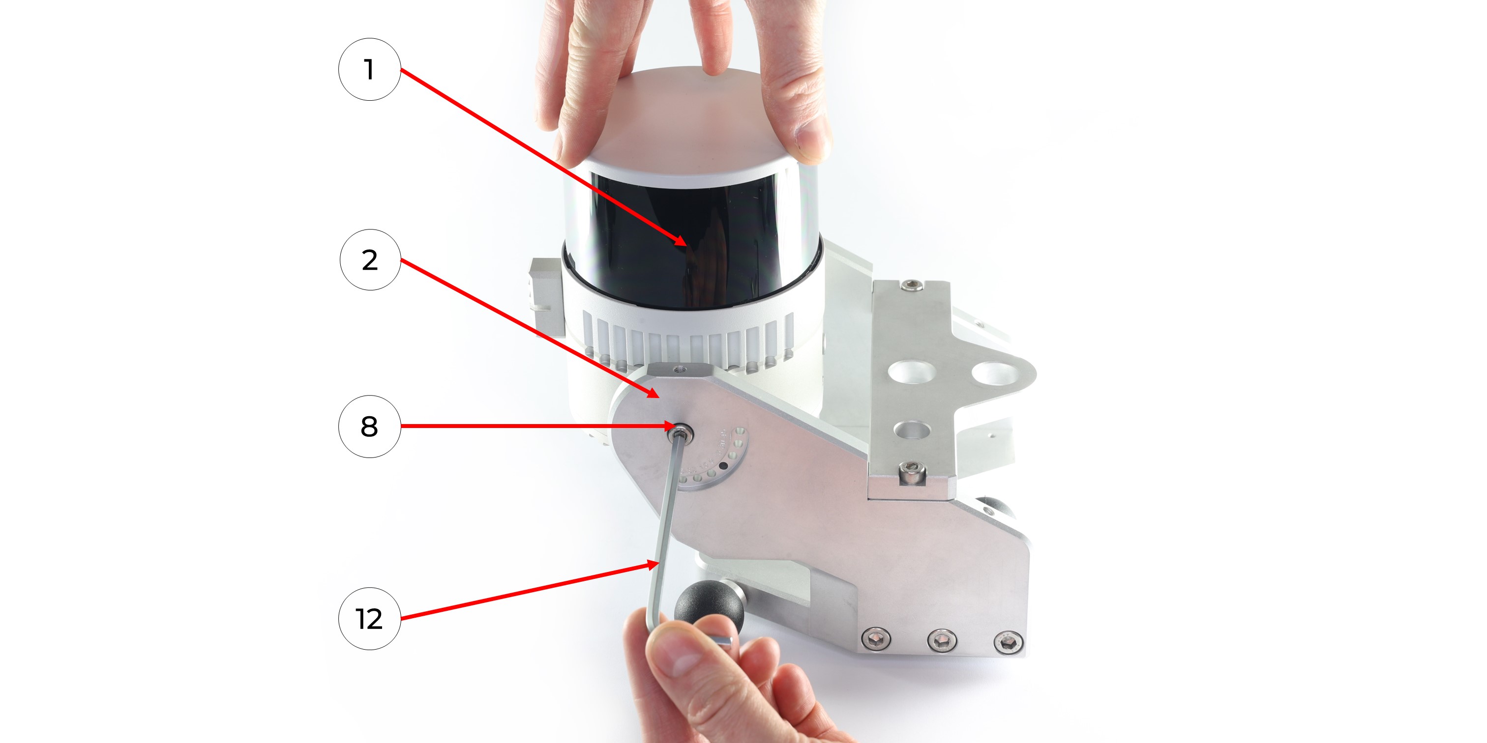 3. Set the TOPODRONE LiDAR (1) at the required angle on the main part of the mobile mount (2) and fix the position with two M3x10 screws (7) using a Hex 2.5 screwdriver (11).
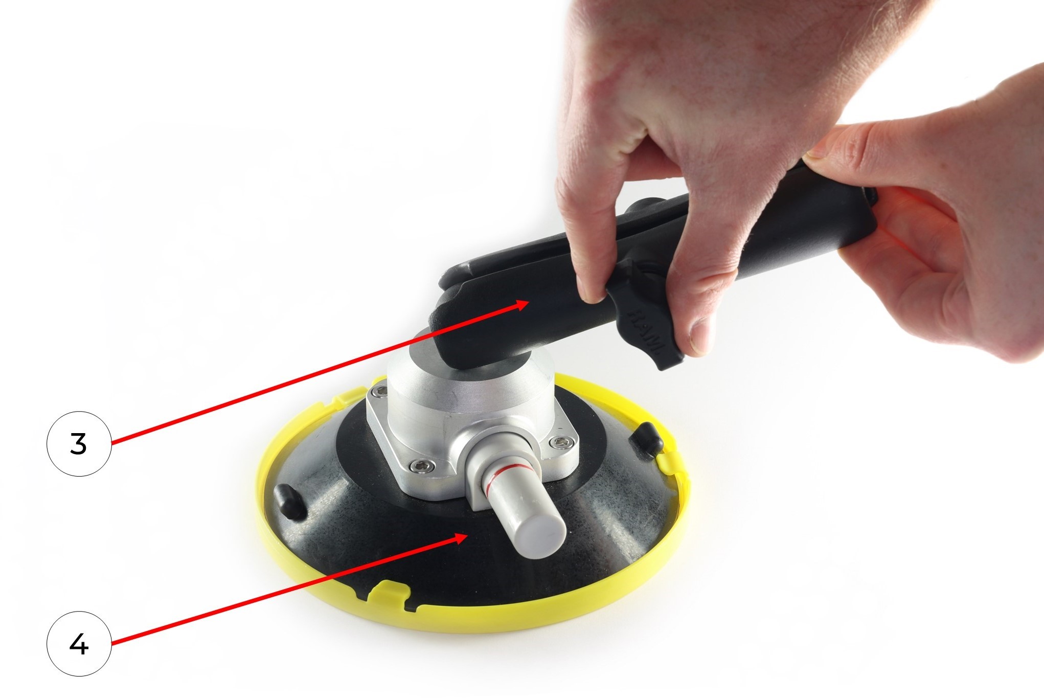
4. Connect the mobile mount arm (3) to the suction cup swivel mechanism (4), repeat with all parts.
5. Connect the mobile mount arm (3) with the other side to the hinge mechanism of the mobile mount base (2). If necessary, manually loosen or tighten the thumbscrew. Once the hinge mechanisms are in alignment, manually tighten the thumbscrew. Repeat with all parts.
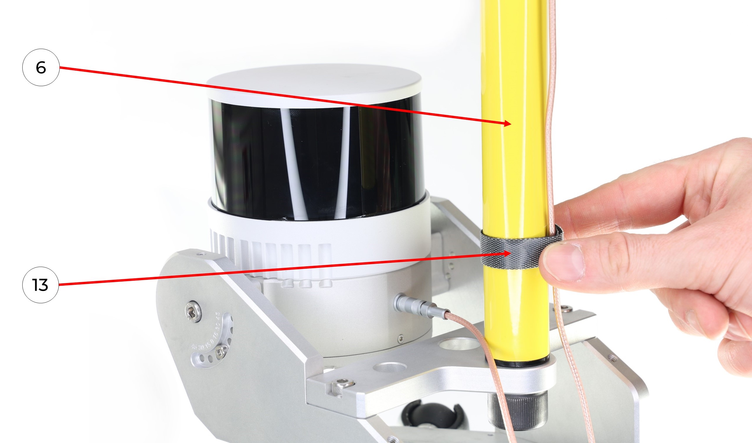
6. Install the pole (6) to the mobile mount base (1). Manually tighten the 5/8" - 11 UNC x 3/4" screw (9).
7. Screw the GNSS antenna (5) onto the pole (6).
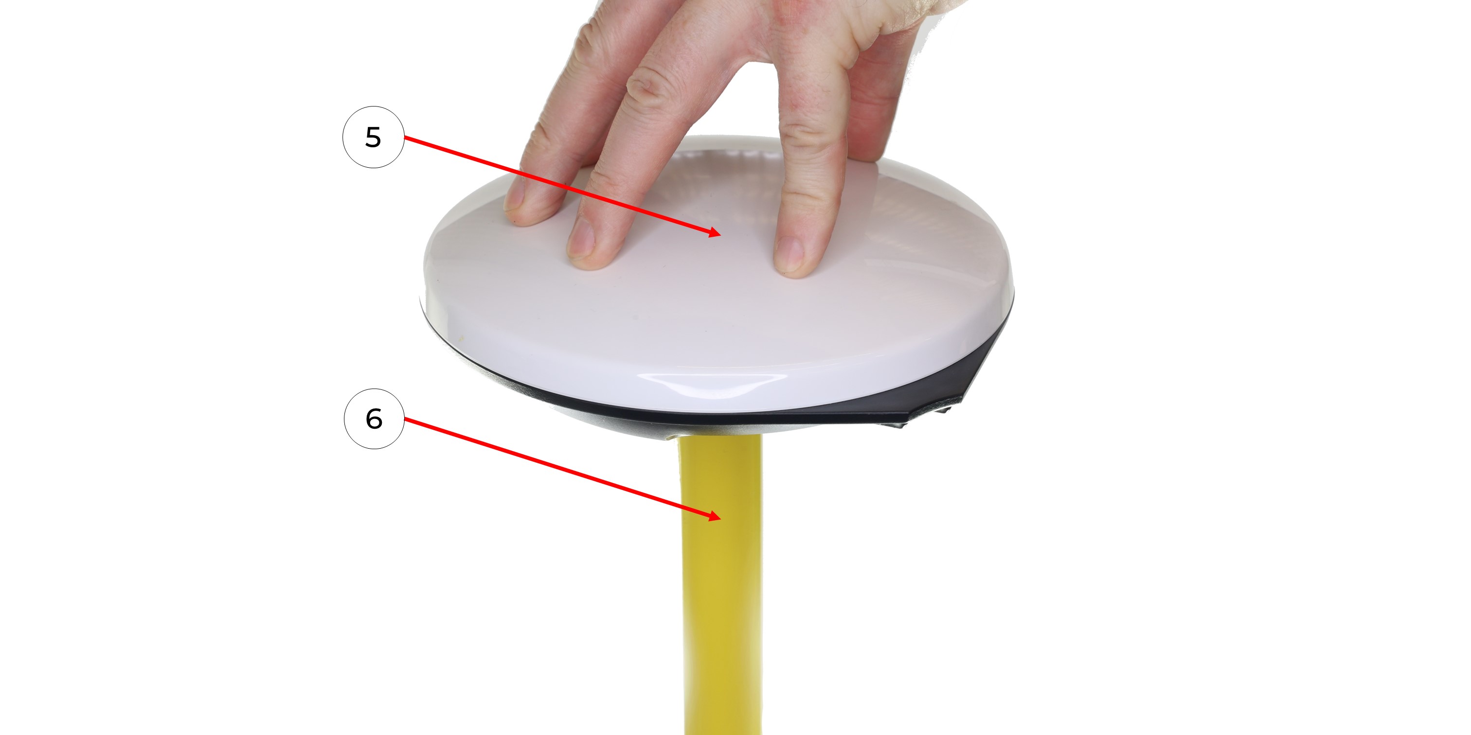
8. Connect the GNSS cable (13) to the GNSS antenna (5), taking care not to bend it.
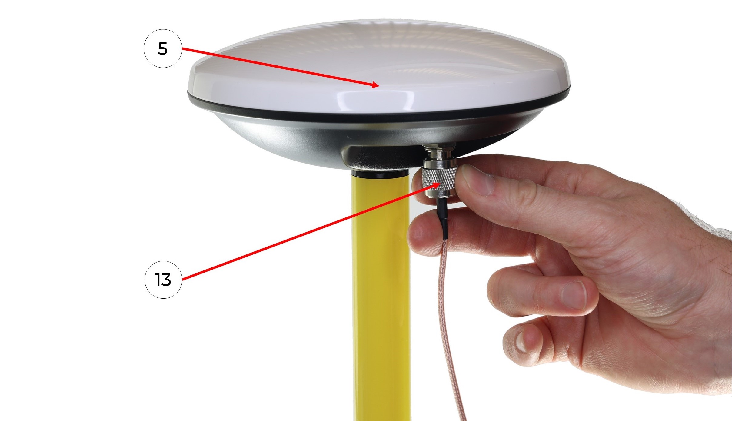
9. Connect the antenna cable with the LEMO connector (13) to the TOPODRONE LiDAR (1) it clicks into place.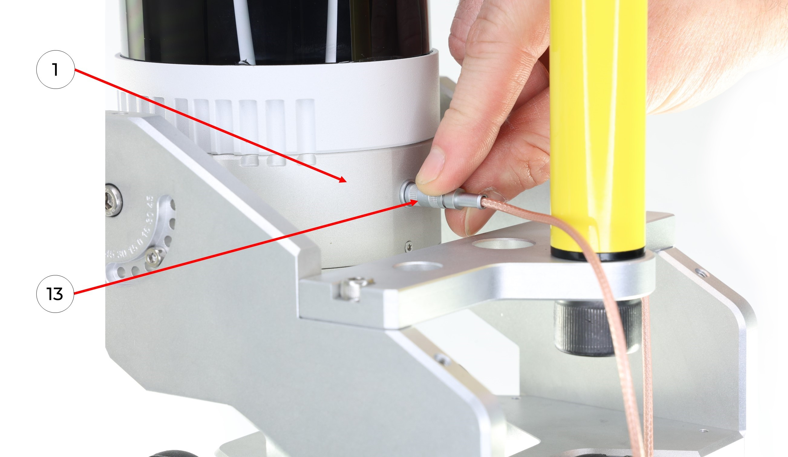
10. It is recommended to fix the antenna cable in the area of the pole (6) with a GNSS cable velcro (13) as shown in the photo.
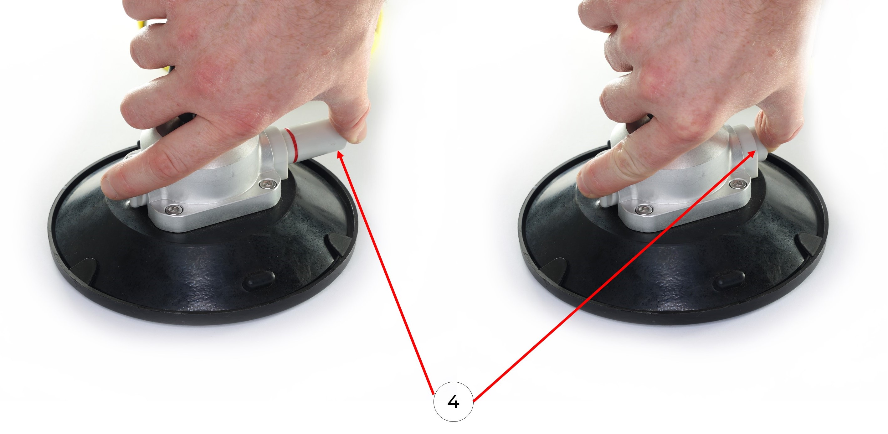
11. Clean the surface of a vehicle with wet and dry wipes. Remove the protective caps from the suction cups (4). Install the mobile mount on the car with the suction cups (4) using the pump. It is necessary to pump the pump until the pump stops pumping out air and the suction cup is completely glued to the surface. The photos below show the process of pumping the air out of the suction cups without removing the suction cup caps.
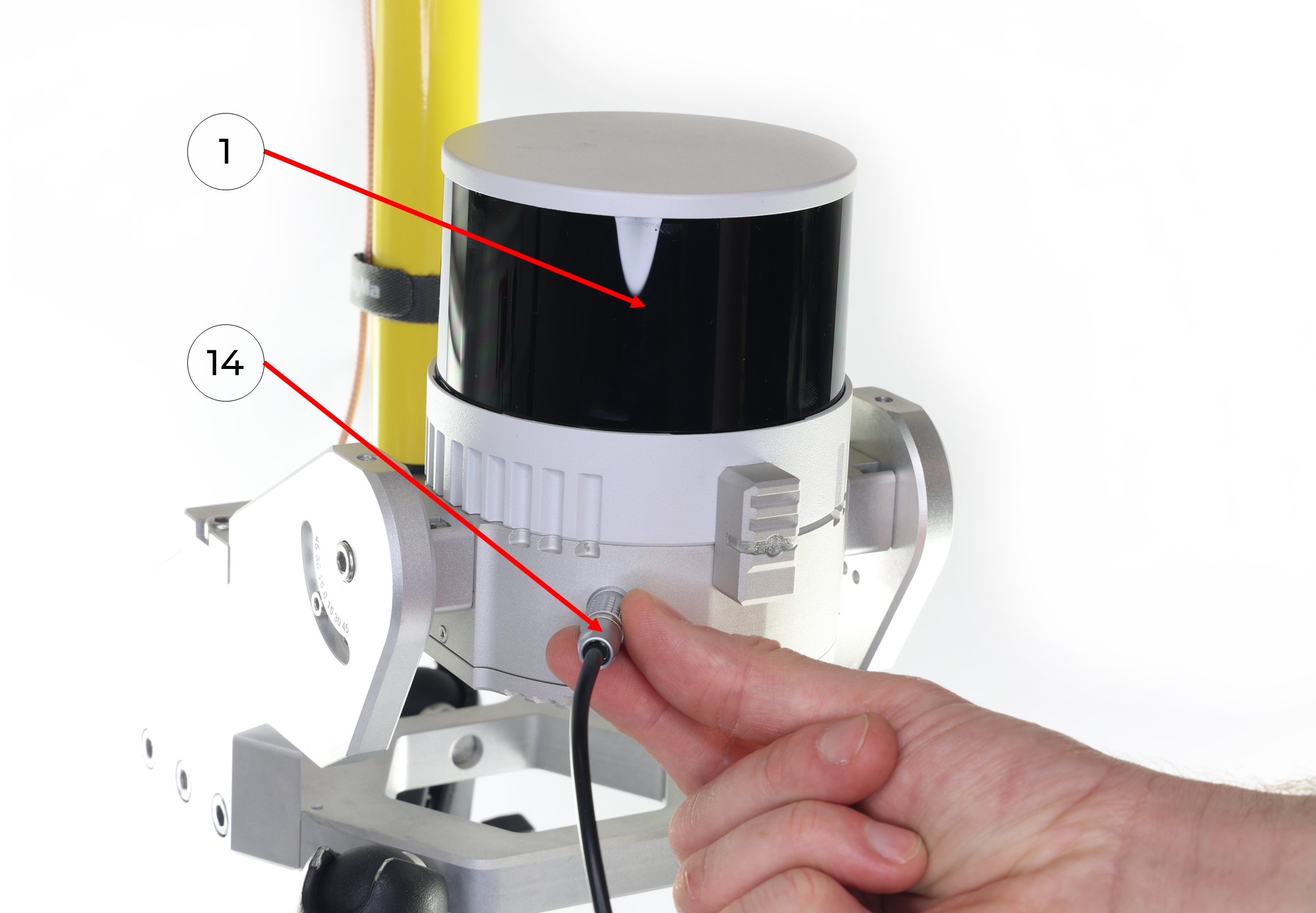
 12. Connect the LEMO 6-Pin connector of power cable (14) to the TOPODRONE LiDAR (1), it clicks into place.
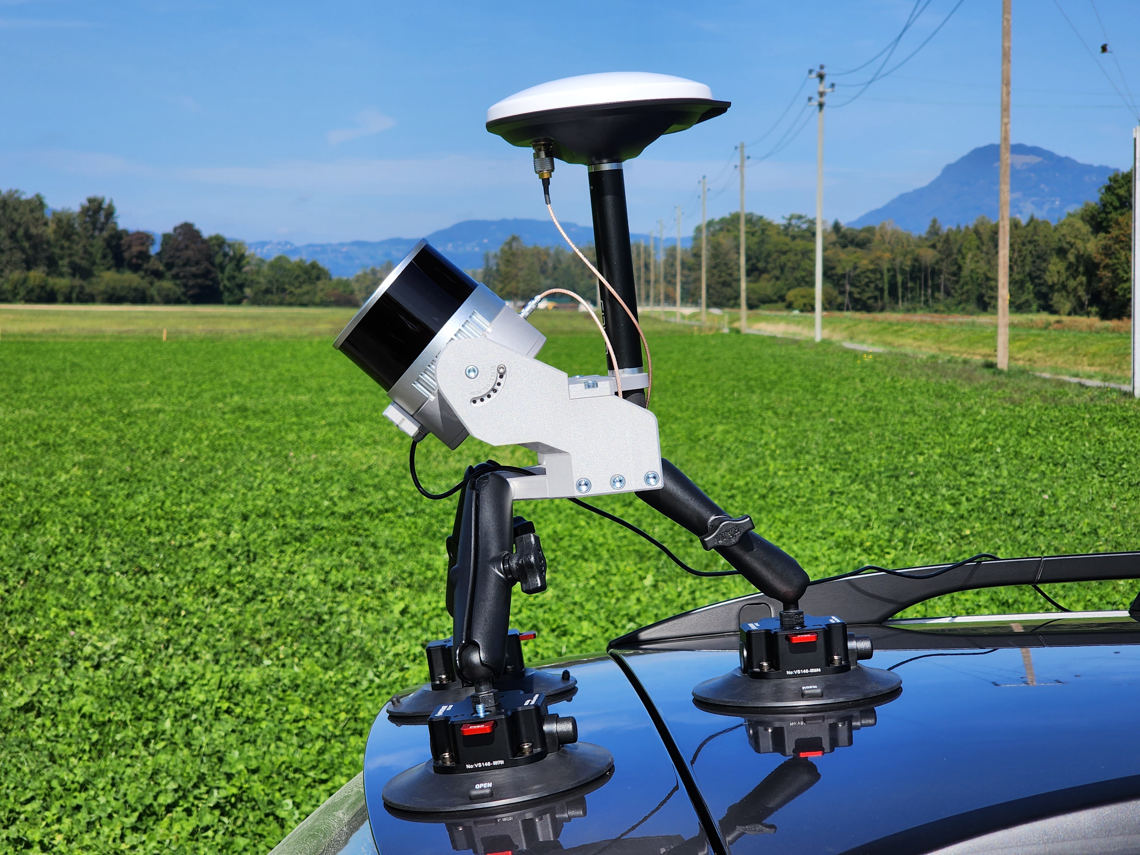
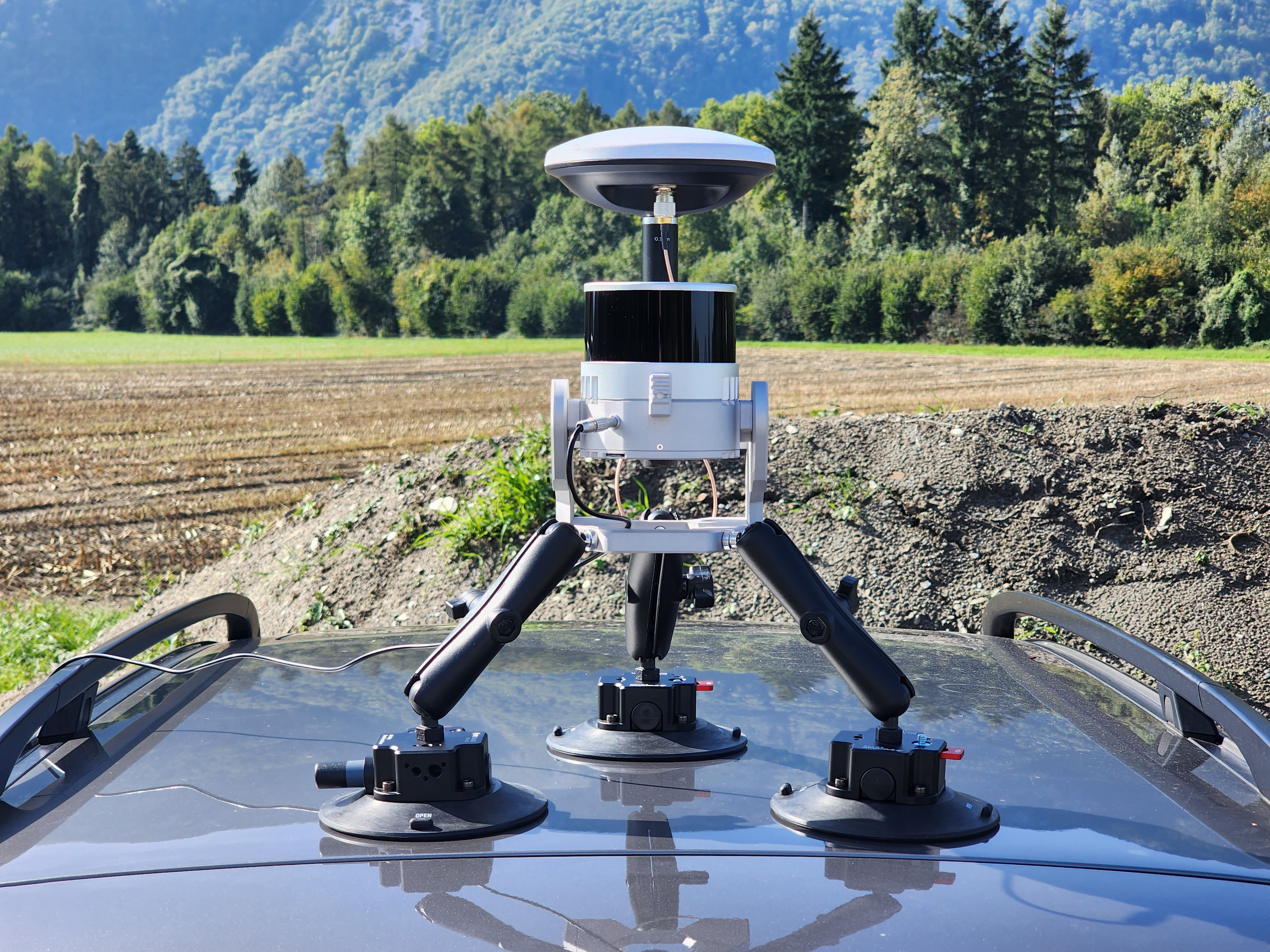
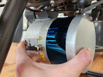
13. If necessary, use the beam wrenches to adjust the position of the mobile mount on the vehicle so that it is level. The photos below show how to mount the TOPODRONE 100+ laser scanner on the vehicle at 30 and 0 degrees respectively.
Note: in the photos below, a non-standard 20 cm long milestone is used, which is different from the one supplied.
 |
|
14. Connect the USB-C port oft the power cable (14) to the Power Bank (15) and apply power. Wait for the TOPODRONE LiDAR to initialize.
It is recommended to check the grip of the suction cups every hour, especially at sub-zero temperatures!
Do not install the suction cups on dirty, dusty surfaces, as well as on joints of planes and parts with seams and gaps.
Assembly of the Mobile Scanning Kit
Additional equipment required for kit assembly:
-
Insta 360 X4 camera;
-
microSD memory card for the Insta 360 X4 camera (128 GB recommended);
-
Camera mounting bracket for Insta 360 X4;
-
Extended antenna cable (70-80 cm);
-
Mounting screw for securing the GNSS antenna;
-
1/4-inch hex socket flat head screw for attaching the camera to the bracket.
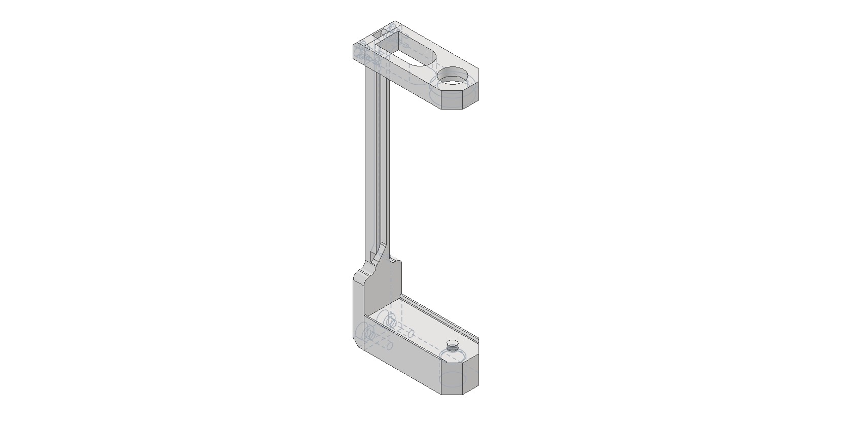
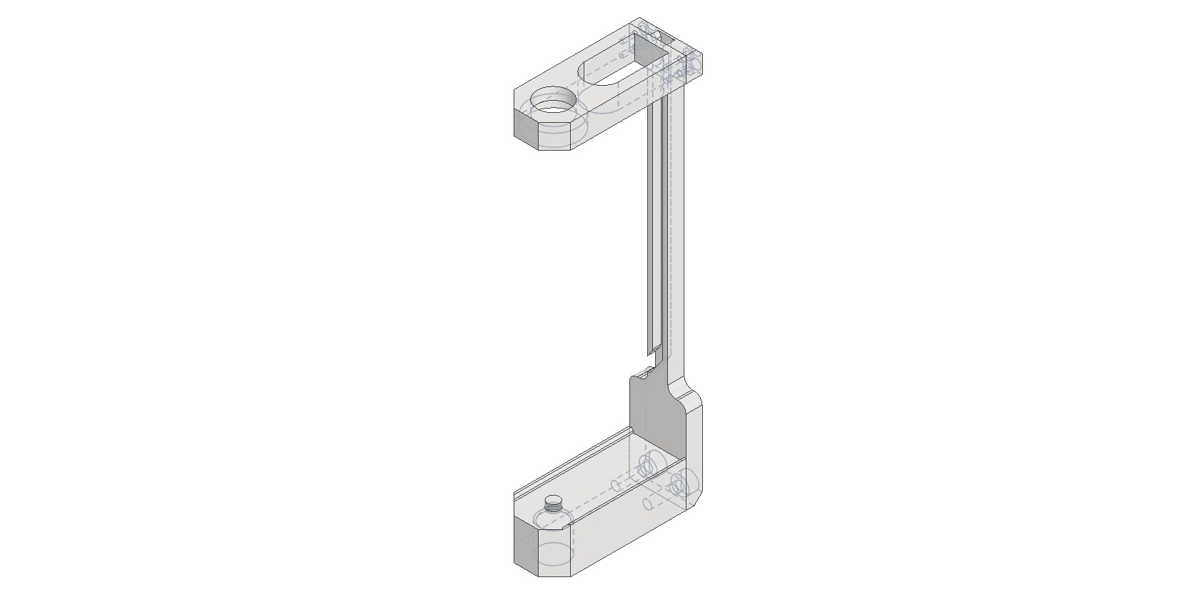
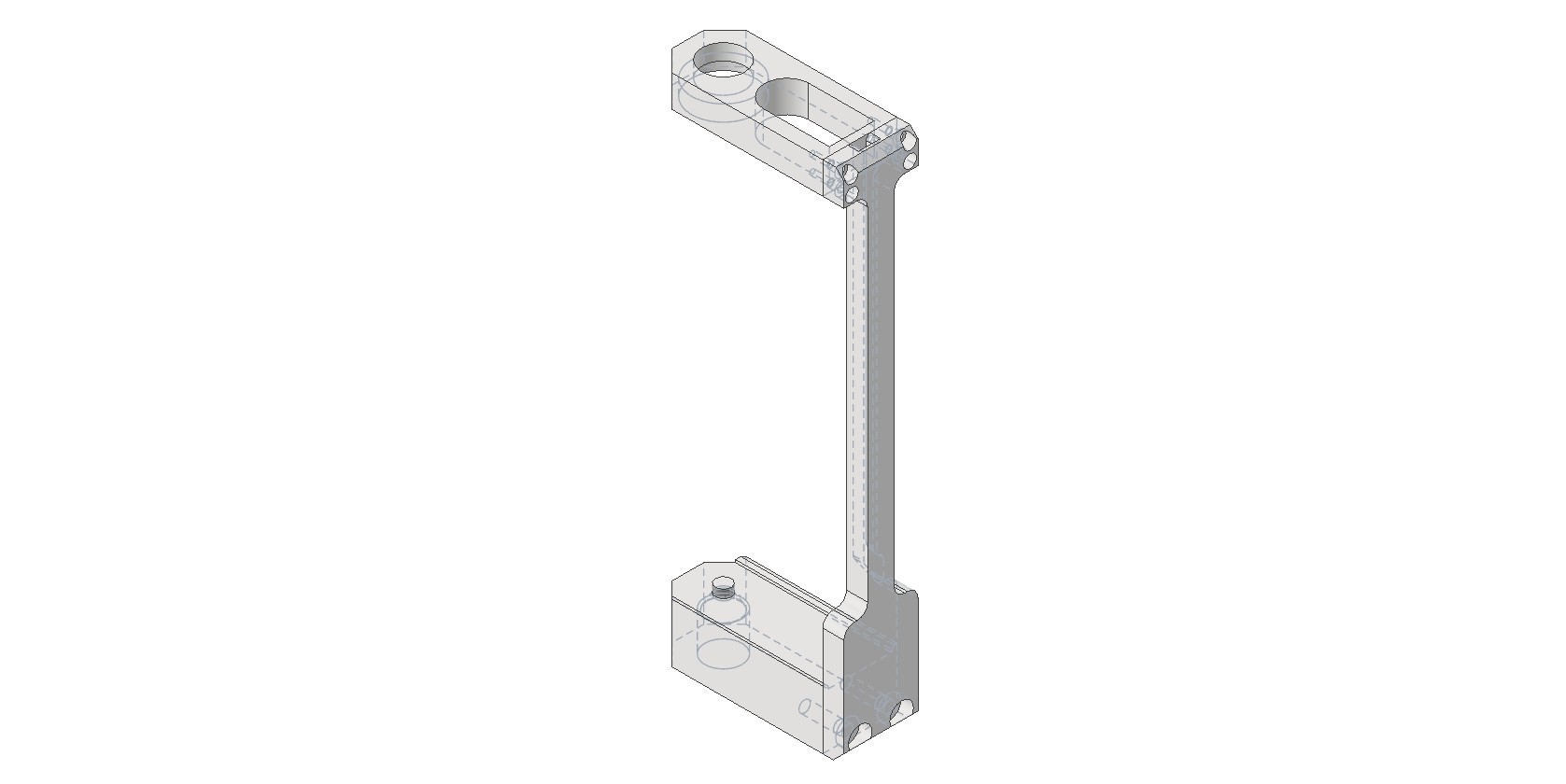
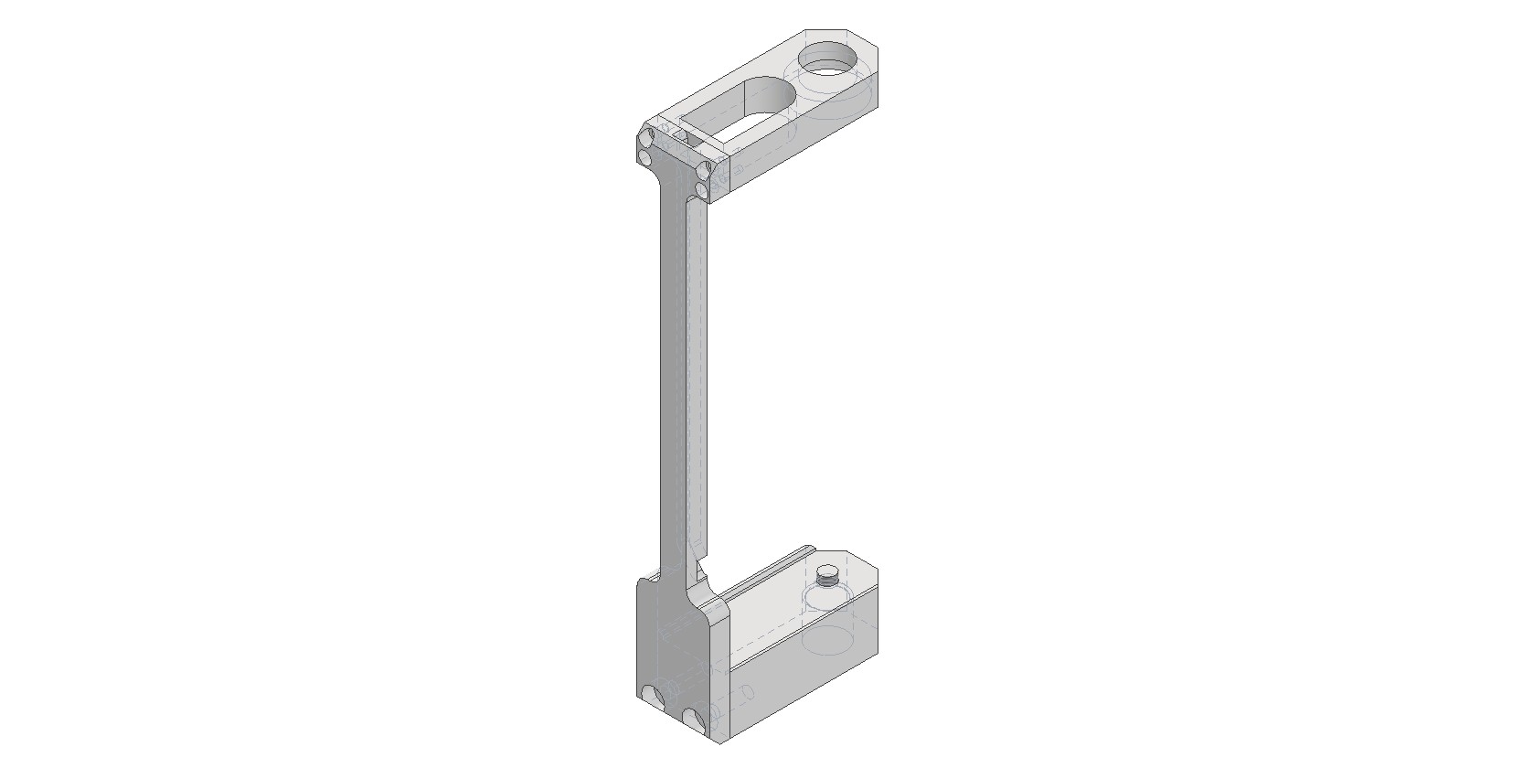
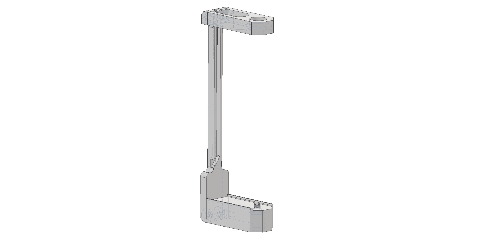
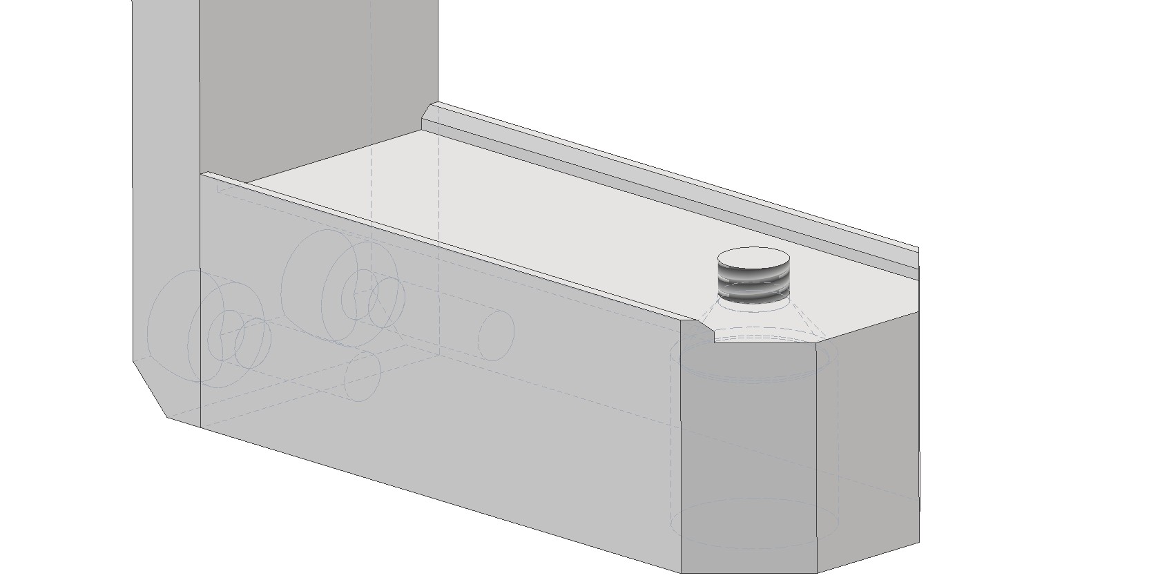
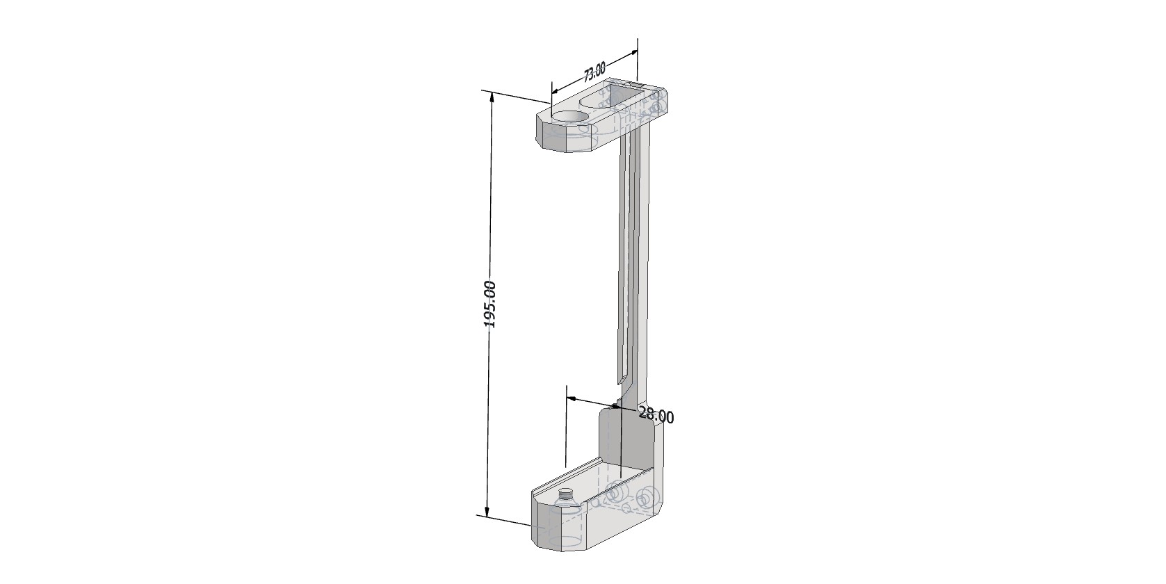
Camera Mounting Bracket Appearance
The bracket dimensions are 195×73×28 mm. The top hole is designed for the GNSS antenna mounting screw. The bottom hole is for the 1/4-inch hex socket flat head screw used to attach the camera to the bracket. The bracket is then screwed onto the pole.
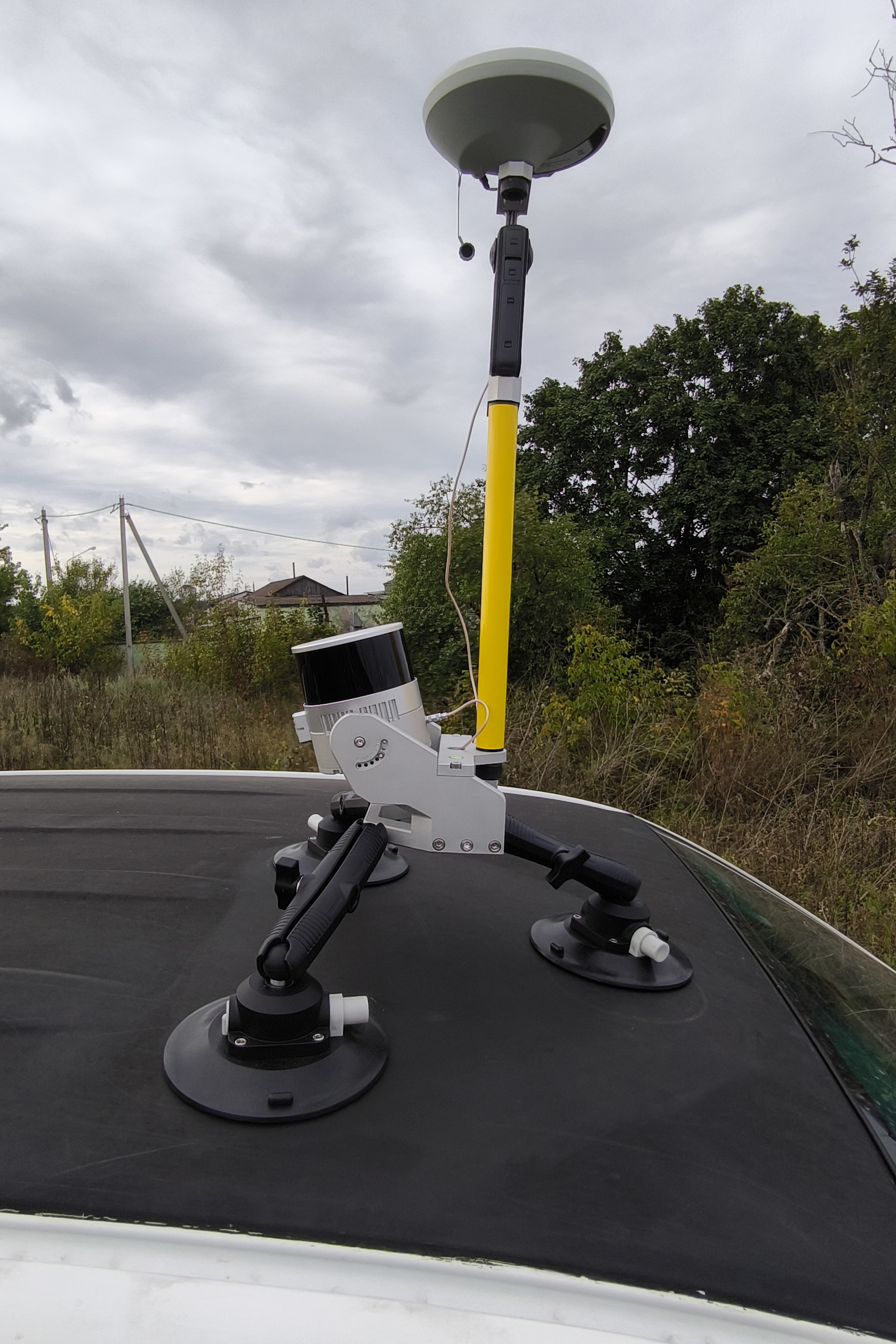
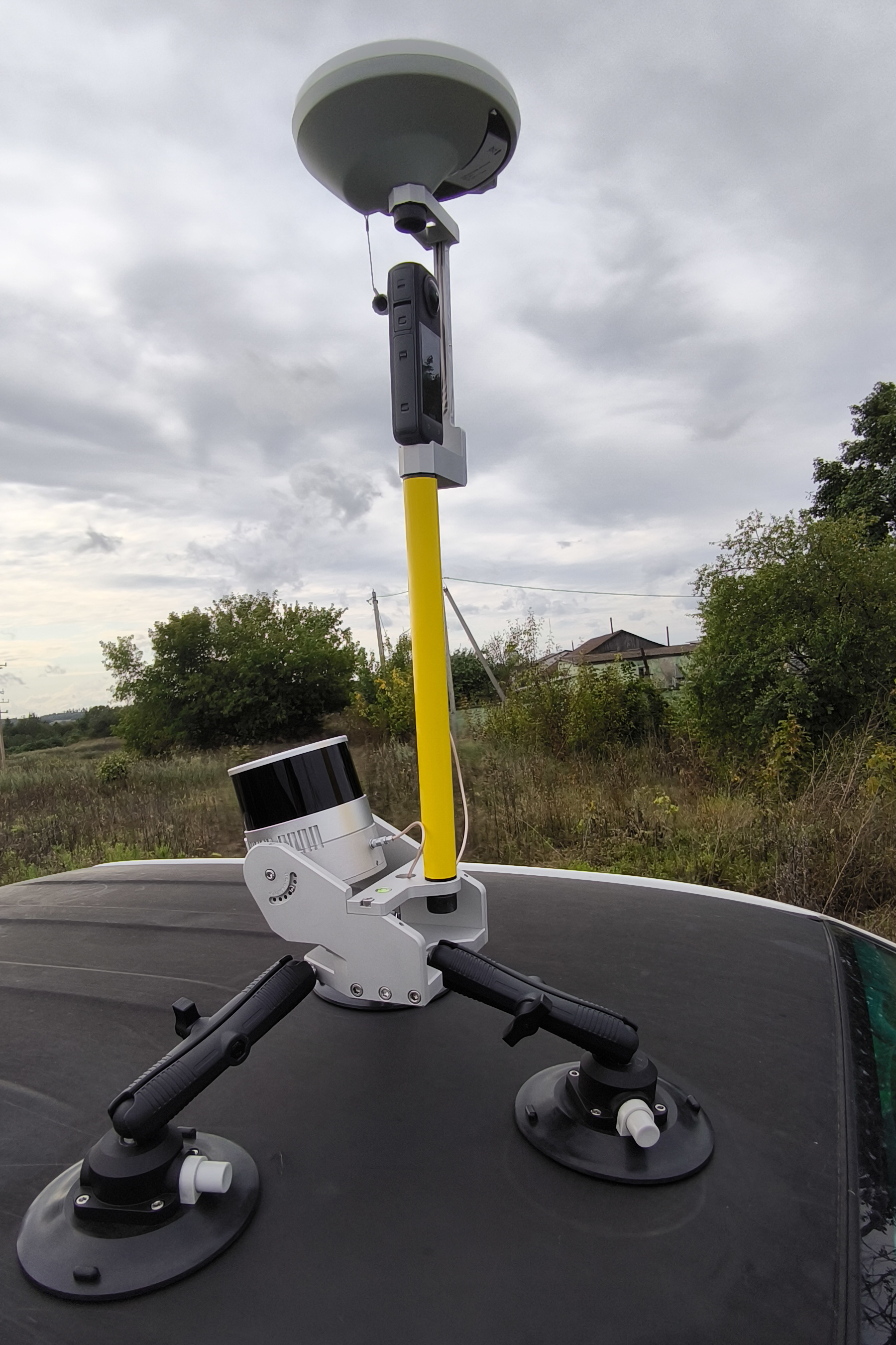
Assembly Procedure for the Insta 360 X4 Camera Shooting Kit
The kit is assembled using the standard procedure, with an additional step for camera installation. Sequence of operations:
1. Install the camera into the bracket.
- Secure the Insta 360 X4 camera in the dedicated bracket using the 1/4-inch hex socket flat head screw.

- Camera orientation: Position the camera so that the optical axis of the lens located on the display side is aligned with the direction of travel of the scanning system.
2. Mount the bracket on the pole.
- Screw the bracket with the attached camera onto the geodetic pole.
3. Install the GNSS antenna.
- Place the geodetic GNSS antenna on top of the bracket and secure it with the standard mounting screw.
- Connect the antenna cable.
Insta 360 X4 Camera Settings
Before installing the camera into the bracket and starting data collection, remove all additional accessories from the camera, such as protective cases and lens covers. The presence of any foreign objects on the camera leads to data defects and is not permitted.
The camera configuration parameters are provided in the table below.
| Setting | Setting value | Setting value |
| Data acquiring mode | Video 360° | Timelapse 360° |
| Scene selection mode | MegaView | - |
| Resolution | 5.7К | 5.7К |
| Frame Rate | 30 | 30 |
| Interval | - | 0.5 |
Data Collection Methodology
The field work procedure is as follows:
-
Assemble the mobile kit with the TOPODRONE laser scanner and camera.
-
Install the mobile kit on the vehicle.
-
Turn on the laser scanner, wait for data recording to begin, then turn on the camera and start video recording.
-
Perform a calibration maneuver and proceed with data collection in the survey area.
-
After completing the survey route, turn off the scanner and the camera.
You can learn more about the mobile laser scanning methodology on the page: Mobile Laser Scanning (MLS)
Installing TOPODRONE LiDAR on DJI Matrice 300 / M350
The following components and tools are required for installation:
|
Version 1, powered by SkyPort connector 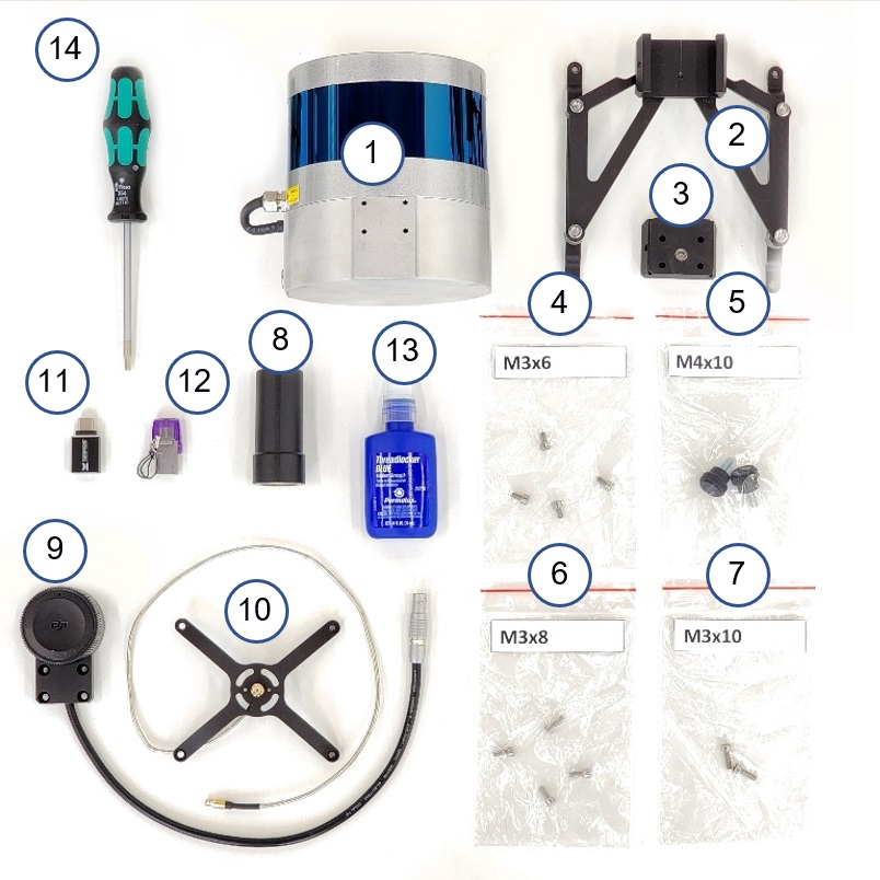
|
Version 2, powered by Type-C connector 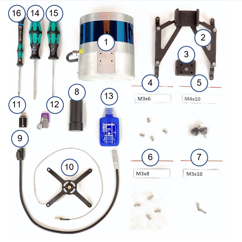
|
* Not included with the TOPODRONE LiDAR.
|
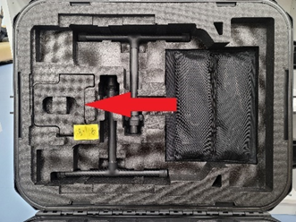
Step 1. Remove the drone's cradle from the case |
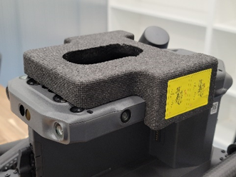
Step 2. Install the cradle on the drone |
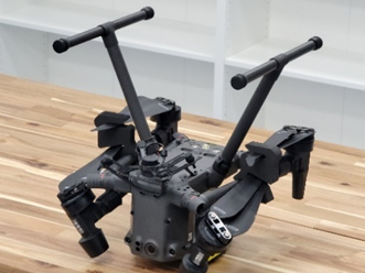
Step 3. Flip the DJM 300 drone |
|
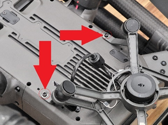
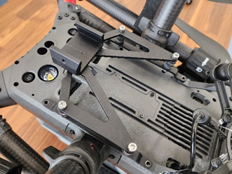
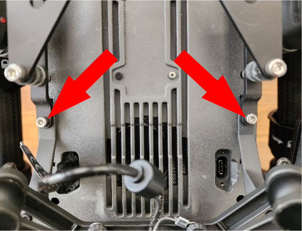
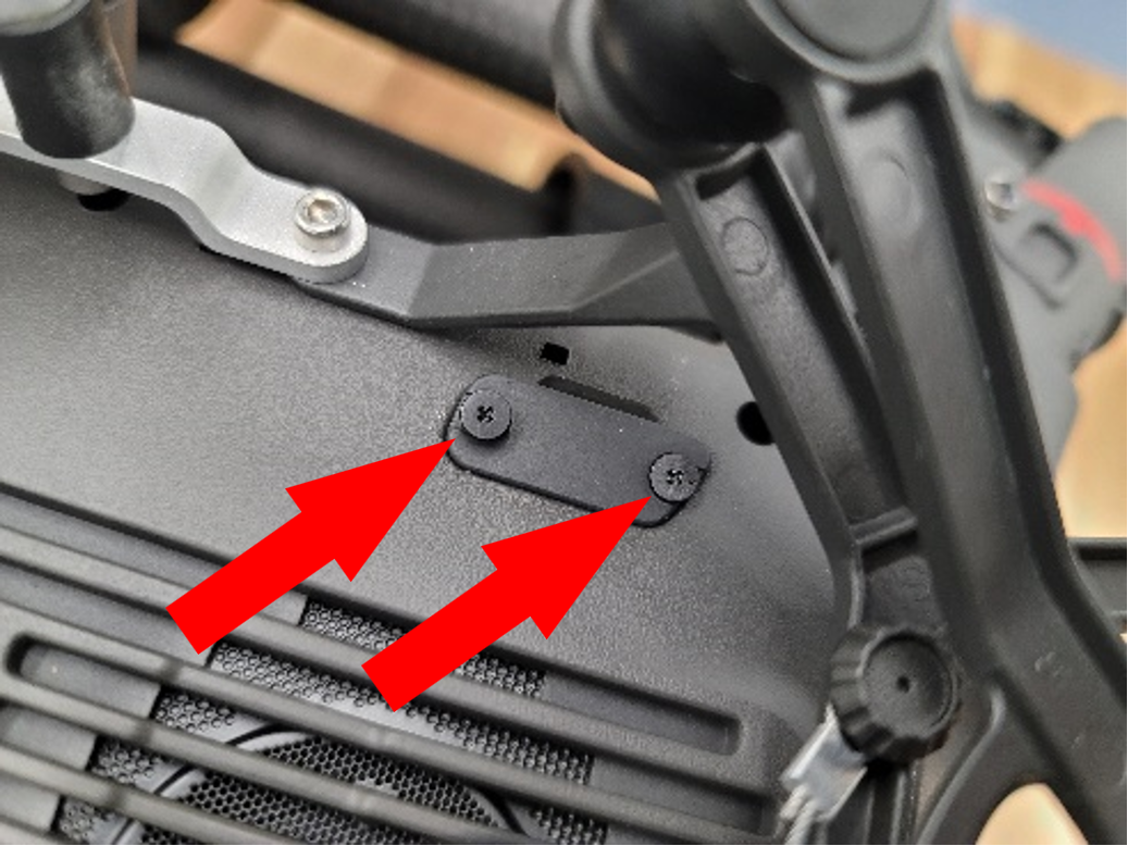
Step 4. Using a 2.5mm Hex screwdriver, unscrew the two black screws and set them aside |
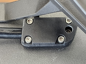
Step 5. Install the mounting pad on the bottom of the drone |
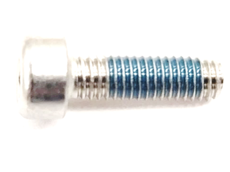
Step 6. Using a 2.5mm Hex screwdriver, screw in 2 M3 x 10 screws |
|
Important! Use the thread retainer in this step! Tighten the screws tightly during installation. |
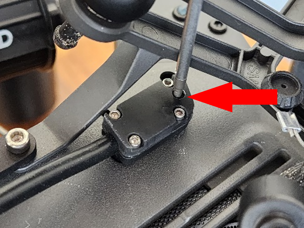
Step 7. Using a 2.5mm Hex screwdriver, screw in the 2 black screws obtained in step 4 |
Important! Use the thread retainer in this step! Tighten the screws tightly during installation. |
|
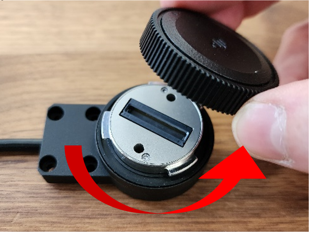
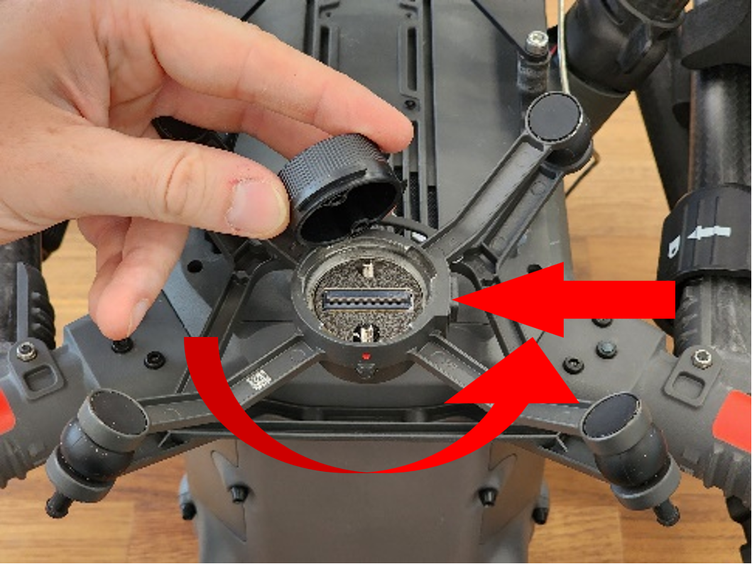
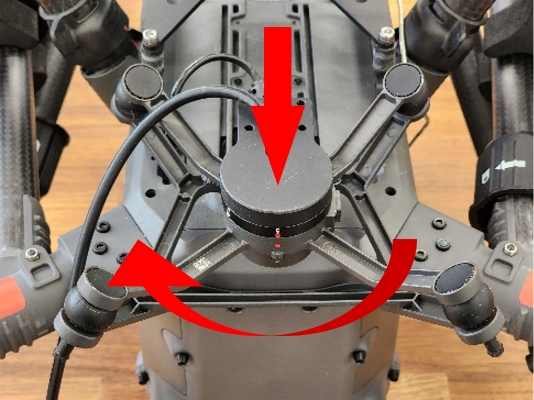
Step 8. (Execution 1). Remove the cover from the SkyPort connector of the LEMO 6 PIN – SkyPort cable |
Step 9. (Execution 1). Remove the cover from the SkyPort connector of the drone |
Step 10. (Execution 1). Connect the cable to the SkyPort connector of the drone |
|
Step 8. (Execution 2). Using a phillips screwdriver, unscrew the 2 screws of the USB Type-C cover |
Step 9. (Execution 2). Install the USB Type-C cable connector into the drone, following the key pattern |
Step 10. (Execution 2). Using a 1.5mm hex screwdriver, tighten the locking screw |
|
Step 11. Turn over the DJI 300 RTK, remove the bed |
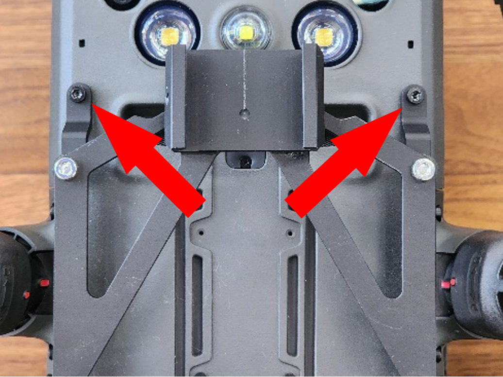
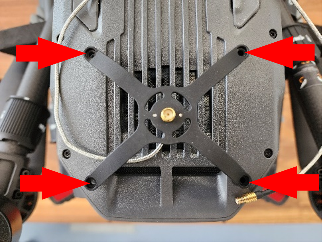
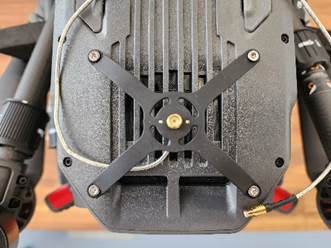
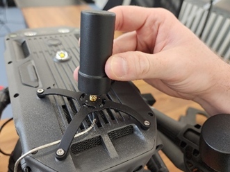
Step 12. Install the "spider" type antenna mount on the top of the drone |
Step 13. Secure the mount using M3x6 screws and a 2.5mm Hex screwdriver. |
|
Important! Use the thread retainer in this step! Tighten the screws tightly during installation. |
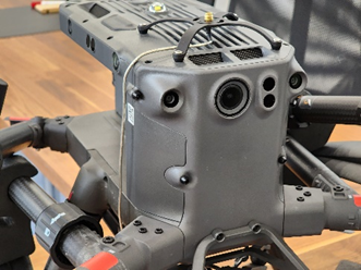
Step 14. Lay the cable along the housing as shown in the photo |
Step 15. Put the TOPODRONE LiDAR on the drone bed, the antenna connector should be on top |
|
Step 16. Install the dovetail mount and tighten the M3x8 screws with a screwdriver |
Important! Use the thread retainer in this step! Tighten the screws tightly during installation. |
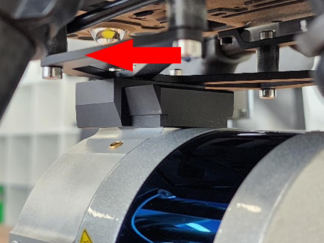
Step 17. Install the TOPODRONE LiDAR on the quick-release mount |
|
It is recommended to install LiDAR from front to back |
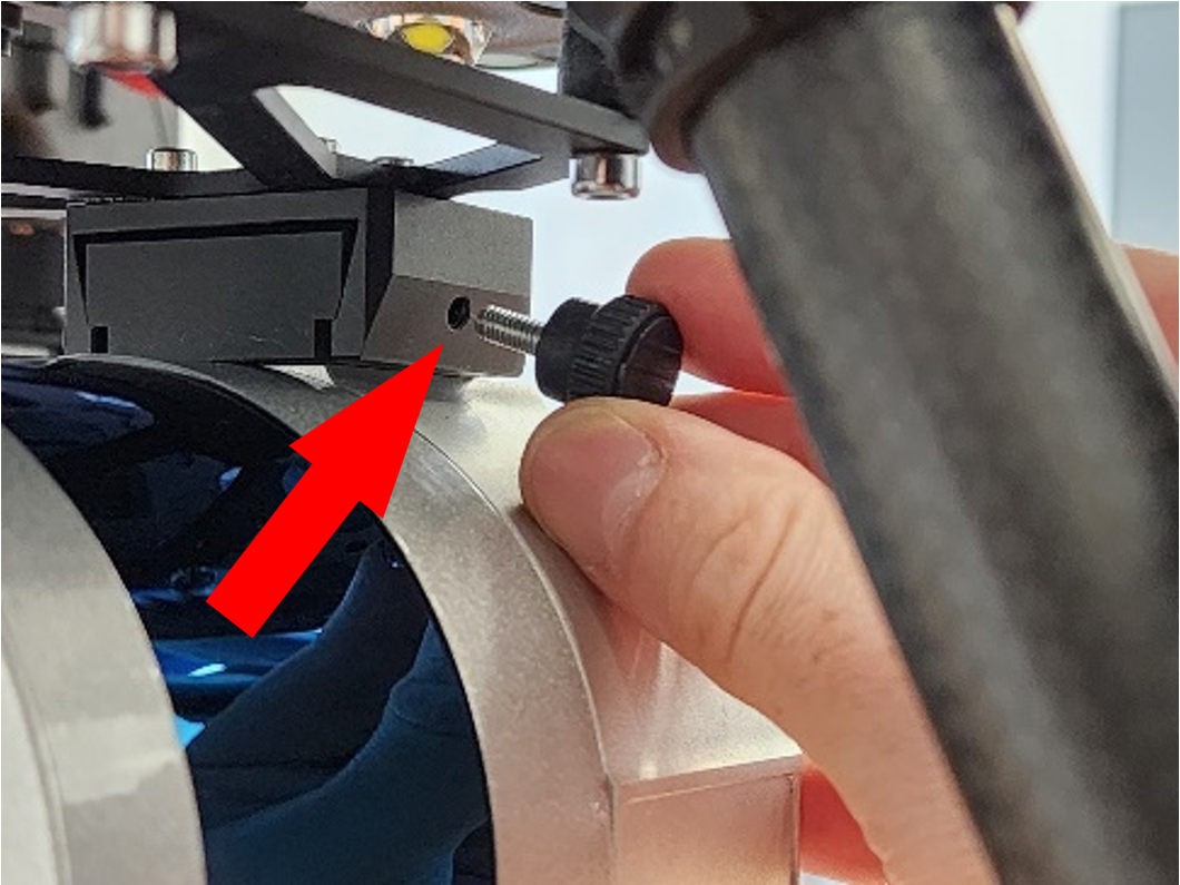
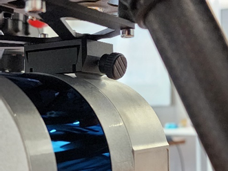
Step 18. Screw in the locking wing screw |
Шаг 19. Винт должен быть закручен плотно, но без чрезмерного усилия |
|
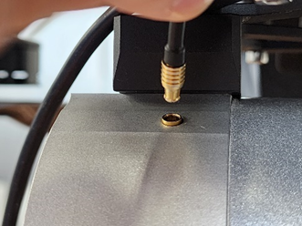
Шаг 20. Подключите антенный разъём к лазерному сканеру |
После подключения антенного разъема он должен выглядеть как на фото |
Step 19. The screw must be screwed tightly, but without excessive force |
|
After connecting the power connector, it should look like in the photo |
Step 22. Screw the GNSS antenna onto the spider-type mounting connector. |
The GNSS antenna should be twisted tightly, but without excessive force |
|
Step 23. In order not to lose the protective caps, you can connect them together |
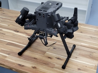
Step 24. The drone assembly with TOPODRONE LiDAR looks like this |
You can start performing ALS |
* Due to the partial overlap of the sensors, the use of a lower visual positioning system with TOPODRONE LiDAR installed is not recommended. It is recommended to land drones during ALS in manual mode to reduce the impact on the landing gear and TOPODRONE LiDAR during landing. The manufacturer is not responsible for the stability of operation of the DJM 300 RTK drone with the lower visual positioning sensors turned on.
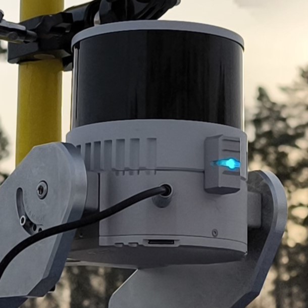
Switching on and initializing the TOPODRONE LiDAR
After correct installation on the drone or backpack, connection of external GNSS antenna and power cable, TOPODRONE LiDAR performs the power-up and initialization procedure. After the initialization a data recording starts on the internal storage of the TOPODRONE LiDAR or on the external memory card if it is installed. The priority of recording on the external memory card. For successful initialization it is necessary to ensure proper installation of the TOPODRONE LiDAR on the appropriate media, the presence of GNSS signal, as well as immobility of the device before the start of data recording.
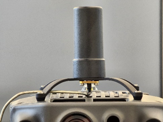
After connecting the TOPODRONE LiDAR to the power supply, it will make a short beep and the LED will turn green. Then, the LED of the laser scanner will light up according to the indication table. If there is a stable GNSS signal and there are no errors, the laser scanner will switch the LED color to constant blue after some time. The succesful TOPODRONE LiDAR LED indication is shown on photos below.
|
|
|
After the initialization, the data is written to the internal memory of the TOPODRONE LIDAR. It is possible to stop data recording by the following events:
- Power interruption, in which case the data will be successfully overwritten due to the internal power system.
- Connecting external media to the USB Type-C port (only available when writing data to the internal memory).
- Running out of free space on the storage medium (memory card or internal memory).
The file system format of the TOPODRONE LiDAR MicroSD is exFAT.
The first activation (cold start) of the laser scanner in an open area with a sufficient GNSS signal level (8 or more satellites) may take more time to pass the initialization procedure than subsequent activations. As a rule, at the first start of the TOPODRONE LiDAR it takes no more than 60 seconds until the start of data recording. In case of subsequent power-ups (warm start) the initialization procedure is faster (20-30 seconds). In case of starting to move along the route, initialization may not be performed correctly during the movement.
It is necessary to check the LiDAR initialization status each time before launching the drone on an automatic mission or starting a walking route, as well as before finishing the work. In case the initialization status at the end of the route is not displayed by the constant LED, it means that the GNSS signal was lost during the route. In this case, the data received from the TOPODRONE LiDAR will be unsuitable for further post-processing.
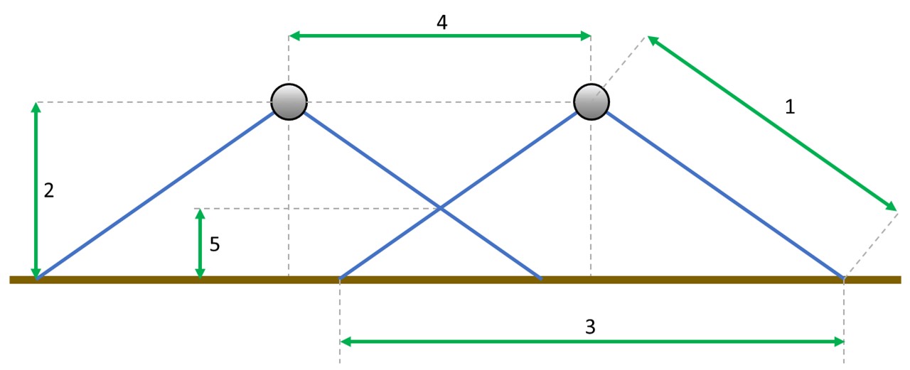
Overlaps between scans and the height of the scanned objects
During the flight, TOPODRONE LiDAR scans an area of the surface of a certain width, which is called a "scan". The width of the scan is determined by the technical characteristics of the sensor, the operating altitude of the flight, as well as the difference in terrain.
For correct postprocessing of the data obtained from TOPODRONE LiDAR, it is necessary that neighboring scans have a common overlap. It is recommended to provide at least 30% lateral overlap to adjacent scans. Insufficient overlap between scans, especially in combination with significant relief differences, can lead to the formation of an area without data, which significantly reduces the quality of output materials.
On the other hand, a higher overlap value allows the most accurate calculation of the calibration angles of Roll, Pitch and Heading. When choosing a specific overlap value, it is necessary to take into account such parameters as the maximum length of the laser beam, the scanning angle (106 degrees for ALS) and the height of the scanned object.
To achieve optimal results when performing ALS using TOPODRONE LiDAR, it is recommended to set the following parameters when building a mission:
|
1 |
2 |
3 |
4 |
5 |
||||||
|
LiDAR model, maximum beam length |
Working height, m |
Scan width, m |
Distance between scan centers: % overlap |
Maximum height of the scanned object: % overlap |
||||||
|
30% |
40% |
50% |
60% |
30% |
40% |
50% |
60% |
|||
|
TOPODRONE LiDAR 100+ и 100 120 m |
50 |
134 |
94 |
81 |
67 |
54 |
15 |
20 |
25 |
30 |
|
60 |
160 |
112 |
96 |
80 |
64 |
18 |
24 |
30 |
36 |
|
|
70* |
187 |
131 |
113 |
94 |
75 |
21 |
28 |
35 |
42 |
|
|
80** |
136 |
96 |
82 |
68 |
55 |
24 |
32 |
41 |
49 |
|
|
TOPODRONE LiDAR 200+ 300 m
|
90 |
240 |
168 |
144 |
120 |
96 |
27 |
36 |
45 |
54 |
|
100 |
267 |
187 |
161 |
134 |
107 |
30 |
40 |
50 |
60 |
|
|
110 |
292 |
205 |
176 |
146 |
117 |
33 |
44 |
55 |
66 |
|
|
120* |
240 |
168 |
144 |
120 |
96 |
36 |
48 |
60 |
72 |
|
|
130* |
260 |
182 |
156 |
130 |
104 |
39 |
52 |
65 |
78 |
|
|
140** |
235 |
165 |
141 |
118 |
94 |
42 |
56 |
70 |
84 |
|
|
150** |
250 |
177 |
152 |
126 |
101 |
45 |
60 |
75 |
90 |
|
Table 1. Dependence of the distance between the scan centers on the overlap and the working height.
* The specifications are given for a scanning angle of 90 degrees.
** The specifications are given for a scanning angle of 80 degrees. With such characteristics, there is a significant decrease in the density of points.
The density of the resulting point cloud depends on factors such as flight speed, altitude, and surface reflectivity. As nominal initial values, it is recommended to conduct flights at a drone flight speed of 6 m/s at an operating altitude of 60 m for TOPODRONE LiDAR 100, 100+ and 100 m for TOPODRONE LiDAR 200+ with 40% overlap.
Further changes to these parameters must be made taking into account the features of the terrain, weather conditions and the maximum height of the scanned objects.
IMU calibration pattern
Before starting each route for ALS or MLS on the TOPODRONE LiDAR, a calibration pattern must be performed after the initialization procedure. This pattern is performed to calibrate the IMU module inside the TOPODRONE LiDAR. Without performing this calibration pattern before starting the route, the data quality may not be satisfactory. During the calibration process on the aircraft, it is necessary to move in a plane at operating altitude in a circular pattern once clockwise and once counterclockwise, the sequence does not matter. An important point is the need to change the spatial position of the TOPODRONE LiDAR, in this regard, the option with rotation around its axis, similar to the compass calibration on DJI drones, is not suitable.
Performing calibration of TOPODRONE ALS laser scanner in automatic mode. There are two ways to perform the figure-eight calibration pattern on DJI drones: automatic and manual. The possibility of automatic execution depends on the flight planning software used. UgCS Pro / Expert software allows you to perform the calibration procedure in automatic mode.
To perform an automatic figure-of-eight flight in UgCS software, follow the steps below:
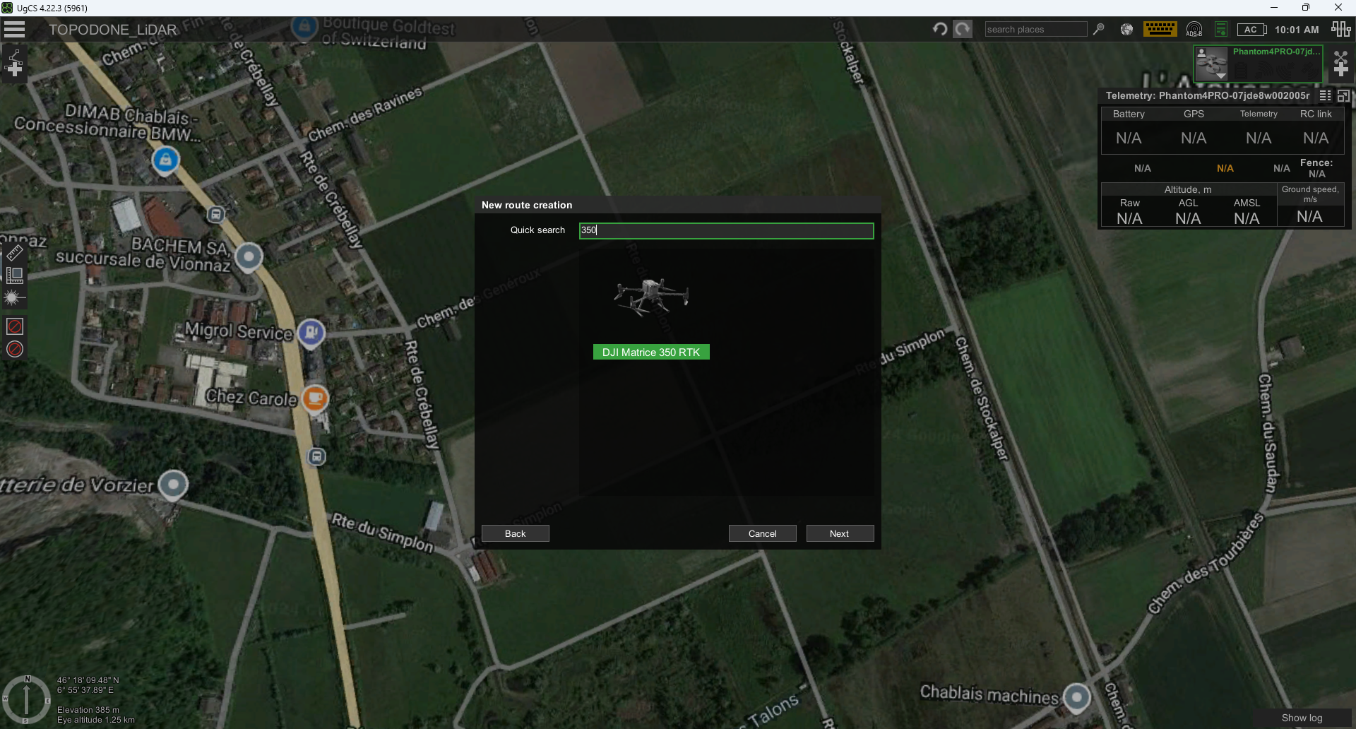
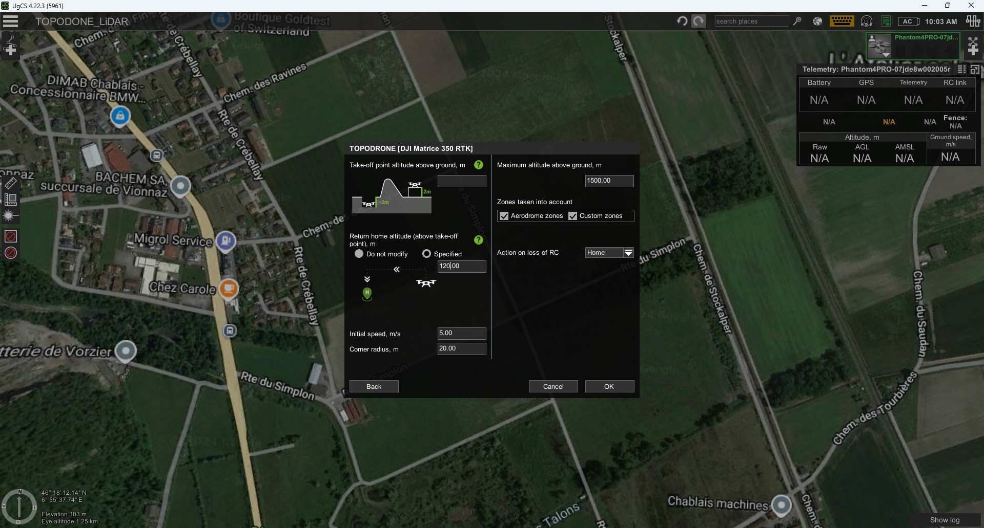
- Create a new route by selecting the desired drone profile and setting the desired parameters for return altitude, actions in case of loss of remote control signal, etc.
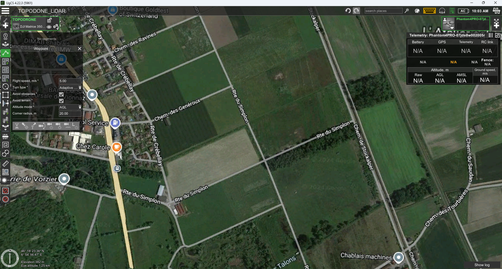
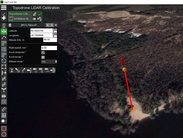
- Using the Waypoint tool, set the takeoff point, which will be the first waypoint of the route. Set the "height above ground" parameter according to the working altitude.

Setting the waypoint before starting the calibration pattern "figure eight" in UgCS Pro / Expert software.
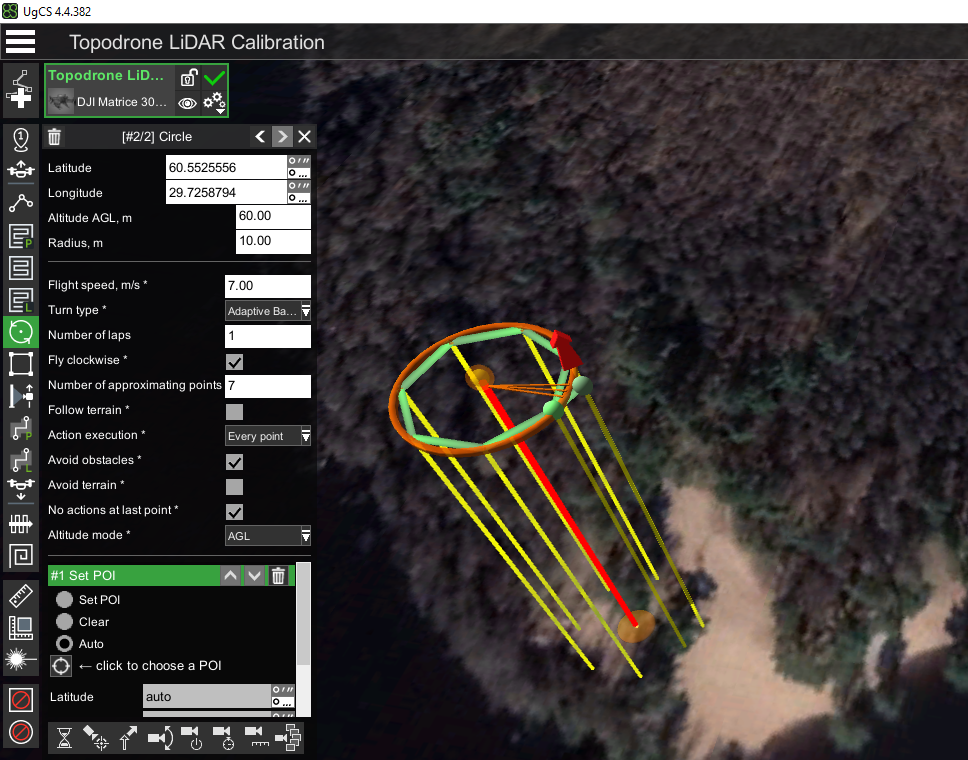
- Using the Circle Flight tool with a double left mouse click, create a circle flight so that it touches the first "Takeoff" waypoint. It is recommended to use/change the following parameters:
- Altitude: 60-120 m according to the working altitude for your sensor (see point 2).
- Range: 10-60 meters
- Flight speed: 6-10 meters per second
- Turn Type: Adaptive Bank Turn (this parameter smooths out corners)
- Clockwise traversal: yes (no for the second lap)
- Number of approximating points: 7
- Follow the terrain: no
- Altitude mode: AGL (altitude will be calculated relative to the terrain)
- POI – delete (by default, the POI orients the drone's front to the center of the circle)

Setting the first circle of the calibration pattern "figure eight" in UgCS Pro / Expert software. Pay attention to the necessity of deleting the POI action
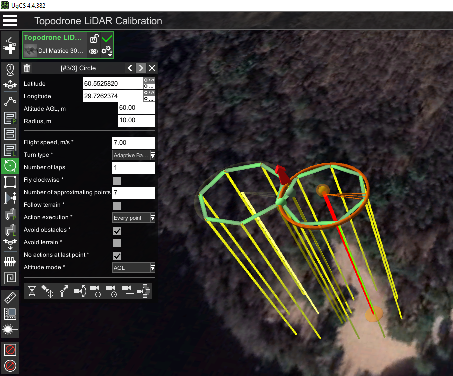
- Using the Circle Flight tool with a double left mouse click, create a second circle flight so that it touches the first waypoint and the first circle. It is recommended to use the same parameters as in step. 3, except for the "Clockwise traversal" parameter, which should be different for the two circles. Clockwise traversal: no (yes for the second circle)

Setting the second circle of the calibration pattern "figure eight" in UgCS Pro / Expert software.
Note the need to fly in circles in different directions.
Calibration of the TOPODRONE ALS laser scanner in manual mode.
If it is impossible to perform the calibration pattern in automatic mode (no UgCS Pro / Expert software), it is necessary to perform this pattern in manual mode before starting the flight along the main route. To do this, perform the following actions:
- Prepare the DJI quadcopter and TOPODRONE LiDAR for use in open terrain, according to the instructions, when there is sufficient GNSS signal strength.
- Turn on the drone, wait for the initialization procedure of the drone and TOPODRONE LiDAR
- Calibrate the DJI quadcopter compass before launching the drone, according to the drone's instructions.
- Performing compass calibration is strictly necessary each time before the first flight on a new terrain.
- Manually in P mode take off to operating altitude.
- When the drone reaches the working altitude, switch to "T" mode - Tripod (if available).
- Perform pattern using the control sticks. To fly in the first circle (clockwise), hold the left stick to the right and the right stick forward. This combination will allow the DJI quadcopter to circle while maintaining altitude. After the drone completes the first circle, without changing the right stick position (forward), change the left stick position to counterclockwise (left).
- In the case of "T" - Tripod mode, you can maneuver the sticks by pushing them to their extremes. Speed limitation and smoothness will be achieved due to the flight characteristics of the "T" Tripod mode. If the Tripod mode is not available in the quadcopter as one of the flight modes, we recommend that you maneuver the sticks as smoothly as possible without sudden movements.
- After completing the second lap pass, the calibration pattern is completed. After completing the calibration procedure of the TOPODRONE LiDAR in manual mode, send the flight task to the quadcopter and start the main part of the flight.
- While performing a figure-eight flight, you can control the turning radius of the drone using the Map view in the app on your mobile device, as well as visually by looking at the drone in flight in the sky.
Performance of the calibration pattern for MLS using TOPODRONE BackPack.
- Prepare TOPODRONE BackPack and TOPODRONE LiDAR for operation in the open terrain, according to the instructions, if there is sufficient GNSS signal strength.
- Make sure there are no objects of any kind within at least 100 meters: buildings, hills, fences, wires, etc. Power up the TOPODRONE LiDAR scanner with the included external battery and power cable.
- Wait for the laser scanner initialization procedure.
- Place the backpack over the operator's shoulders.
- Walk at a constant speed of 5-9 km/h in two circles with a radius of 10-15 meters clockwise and counterclockwise. Each circle must be closed before the start of the next stage.
- After completing the second lap pass, the calibration pattern is complete. You can proceed to the main task.
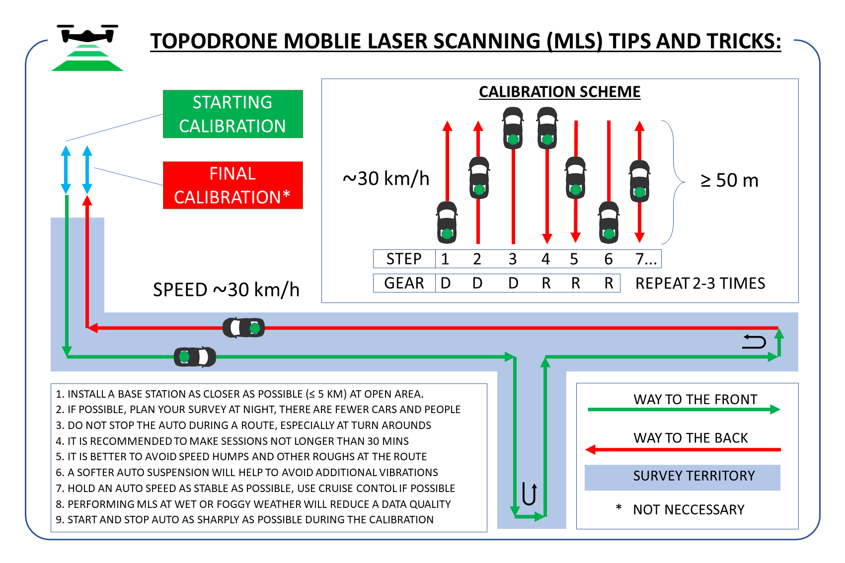
Performing the calibration pattern for the MLS when using a vehicle mount.
- Prepare the TOPODRONE car mount and laser scanner for operation in the open area according to the instructions, if there is a sufficient GNSS signal level.
- Make sure there are any objects within at least 100 meters: buildings, hills, fences, wires, etc.
- Place the car mount together with the laser scanner on the roof of the car in such a way that the cable coming out of the sensor and going into the TOPODRONE housing should face backwards in the direction of travel.
- Power up theTOPODRONE LiDAR scanner with the included external battery and power cord.
- Wait for the laser scanner initialization procedure.
- Perform a drive at a constant speed of 20-30 km/h forward for a distance of 50-100 meters with a return to the starting point in reverse at the same speed. Repeat this step 2-3 times.
- Once the passes are completed, the calibration pattern is done. You can proceed to the main task.
Airborne Laser Scanning (ALS)
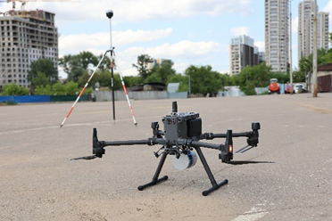
The TOPODRONE LiDAR is designed to perform airborne laser scanning (ALS). To perform this procedure, you will need a drone that supports the correct installation of the TOPODRONE LiDAR and is capable of following a planned flight path. One such drone, for example, is the DJI M300/350 RTK.
TOPODRONE LiDAR ALS rules:
1. Neighboring spans (hereinafter for simplification - scans) should have a lateral overlap of 30% or more. 2.
2. Scans should be parallel to each other
3. The drone must follow neighboring scans in forward and reverse directions
4. The movement speed of the drone with the TOPODRONE LiDAR on the main section of the ALS should be constant
5. The distance from the TOPODRONE LiDAR to the ground surface shall be constant
6. To obtain correct ALS data, it is recommended to take at least two scans
7. Use original propellers to reduce vibration
8. Do not fly in squall winds or during precipitation to reduce noise
9. After initializing the TOPODRONE LiDAR and taking off, perform a calibration maneuver before the main ALS section of each flight
10. If the flight takes more than 30 minutes, it is recommended to perform the calibration maneuver again when the session time reaches 30 minutes after turning on the TOPODRONE LiDAR.
ALS and the terrain elevation:
At insignificant height differences at the ALS location (up to 10 meters) it is allowed to fly the drone with TOPODRONE LiDAR at a fixed altitude (AMSL). The altitude of the drone flight is set relative to the altitude of the takeoff point. Accordingly, for the main part of the flight, almost any software can be used, allowing to set the flight on a circle (to perform the calibration maneuver), as well as to set the distance between parallel passages.
If altitude differences at the ALS location (10 meters or more) are exceeded, it is necessary to use software that supports the “elevation envelope” (AGL) function for ALS route planning. The most convenient way to plan such routes is to use UgCS Expert software.
This is an example of UgCS Expert software and DJI M300/M350 RTK:
- Install UgCS Expert software and open it.

- Create a new mission and create a route for the DJI M300 RTK or DJI M350 RTK drone profile