
TOPODRONE LiDAR design and overview
TOPODRONE LiDAR 100/100+/200+ is a multifunctional device designed for airborne and mobile laser scanning (ALS and MLS) of the earth's surface. The main task of the TOPODRONE LiDAR is to acquire data to generate a dense cloud of terrain points, which in turn allows the classification and processing of this data. The obtained data can be used for various tasks such as geodesy, cartography, volume measurement, taxation and monitoring of various objects.
TOPODRONE LiDAR can operate in a variety of environments, including dense grass, forest or urban areas, under all lighting conditions. However, for effective operation of TOPODRONE LiDAR it is necessary to have sufficient Global Navigation Satellite Systems (GNSS) signal. The use of SLAM technology in the post-processing software TOPODRONE Post Processing allows you to get highly accurate data even in the presence of a weak GNSS signal on the main trajectory.
In the process, to obtain optimal results, the laser scanner should cover certain areas of the ground surface with at least 30% overlap (106 degrees under the UAV in VLS, and 360 degrees around in MLS).
Subsequently, the data from the laser scanner are processed sequentially in several software to equalize the data, align the scans, filter out noise, classify the point cloud, and produce the final materials:1
1. TOPODRONE Post Processing, which calculates a high-precision laser scanner trajectory, generates a dense raw point cloud and initially aligns the scans to each other (Strip Alignment).
2. LiDAR360 software, which performs high-precision alignment of scans to each other (Strip Alignment) and applies several filters to reduce noise and improve the accuracy of the final point cloud. LiDAR360 software can then classify the point cloud and generate final materials (DEM, DEM, etc.).
Further post-processing of data from TOPODRONE LiDAR is performed in the software that is necessary to fulfill the final tasks for a particular user.
Application of SLAM technology in TOPODRONE Post Processing software allows you to get highly accurate data even in the presence of weak GNSS signal on the main trajectory.
TOPODRONE PPK GNSS receiver integrated into TOPODRONE LiDAR, together with high-precision inertial measurement unit (IMU) allows to obtain high-precision coordinates of the TOPODRONE LiDAR trajectory after post-processing, as well as high-precision coordinates of photo centers from TOPODRONE P24 / P61 cameras, synchronizing both devices by cable. GNSS receiver records “raw” GNSS measurements in *.UBX format and time stamps of the TOPODRONE P24 / P61 camera shutter, if it is connected.
Operation of TOPODRONE LiDAR without GNSS signal is not possible.
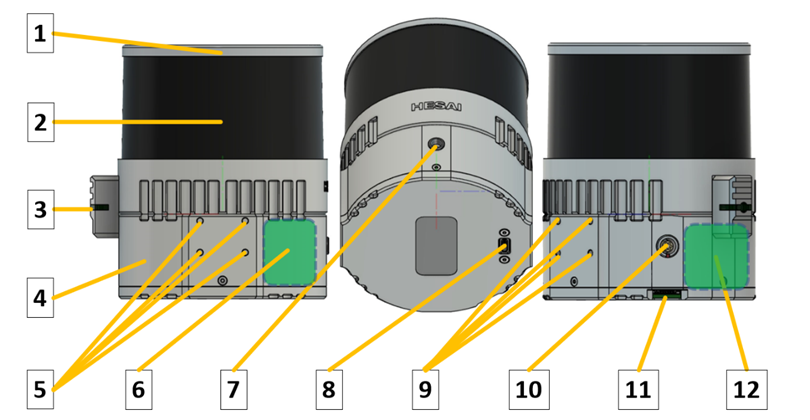
TOPODRONE LiDAR 100 / 100+ / 200+ is based on the following modules and systems:
-
LiDAR sensor housing;
-
Sensor lens;
-
Operation status LED;
-
TOPODRONE LiDAR housing;
-
Mounting holes with M3 thread;
-
High precision inertial measurement unit (IMU);
-
LEMO FFA.00 connector for external GNSS antenna cable connection;
-
USB Type-C 2.0 connector;
-
Mounting holes with M3 thread;
-
LEMO 6 pin connector;
-
Micro-SD memory card slot;
-
GNSS receiver TOPODRONE.
Description of TOPODRONE LiDAR 100 / 100+ / 200+ components:
1. LiDAR Hesai sensor housing. Made of aluminium alloy, coated with grey enamel. During operation, the housing may slightly vibrate and make sounds and may heat up to 60°C. This effect is caused by the rotation of the scanning units of the laser heads inside the case, as well as heat dissipation from the working internal components.
2. LiDAR Hesai sensor lens. It is made of glass with polymer anti-reflective coating. It acts as a filter that transmits light only in the working wavelengths of the laser, as well as mechanical protection of the scanning rotating laser heads of the sensor. The coating of the laser scanning sensor lens is vulnerable to scratching and chipping. It is strongly recommended that the TOPODRONE LiDAR lens be treated with care and not be operated under conditions that could damage or scratch the surface of the laser scanning sensor. If scratches and damage occur, the quality of the acquired data may deteriorate. Individual single minor scratches do not generally reduce the quality of the data.
3. TOPODRONE LiDAR status LED. Displays the current operating status of the device. Below is the decoding of the light signals:
|
Switching on and off |
||
|
1 |
Infrequent green flashes | Charging Ionistors Normal ~10 seconds |
|
2 |
Flashing green |
Linux booting |
|
3 |
Flashing red, siren |
After 1 minute of flashing green |
|
4 |
Green |
Linux booted, waiting for services |
|
5 |
Rapid flashing green |
After power off, shutdown. Normal ~10 seconds |
|
Waiting for and recording data |
||
|
6 |
Green |
System initialisation |
|
7 |
Siren, flashing red |
Hardware problem with Ublox or IMU |
8 |
Green flashing orange |
Waiting for GNSS signal The better the signal, the faster the flicker |
|
9 |
Green |
Time setting Normally ~ 1 c |
|
10 |
Green flashing blue |
Start recording Normally ~ 10 s |
|
11 |
Triple signal, blue |
Recording |
|
Copying data (after connecting a USB stick) |
||
|
12 |
Green |
Recording stopped Normal ~ 1 c |
|
13 |
Flashing crimson, rising tone signal |
Start copying |
|
14 |
One flash red, siren |
Error mounting the USB stick Faulty USB stick or file system |
|
15 |
Two flashes red, siren |
Not enough space on the USB stick |
|
16 |
Flashing crimson |
Copying data Flickering speeds up during copying process |
|
17 |
Fast flashing red, siren |
Write error |
|
18 |
Green, decreasing tone signal |
All data copied |
4. TOPODRONE LiDAR housing. Made of aluminium alloy for better heat transfer and weight reduction. It is the main supporting structure of the LiDAR.
5. M3 fixing holes are made inside the aluminium body of TOPODRONE LiDAR for attaching it to a backpack or car mount.
6. The IMU (Inertial Measurement Unit), a high-precision inertial measurement unit, is used to record lateral and radial accelerations and inclination angles of the LiDAR during ALS and MLS operations. The data from the IMU is required for use in the post-processing phase for flight path equalisation. Antenna offsets are calculated from the centre of the IMU to the phase centre of the external GNSS antenna. Honeywell and Epson IMUs are used.
7. LEMO FFA.00 connector for connecting an external GNSS antenna. It is used for ALS and MLS. When performing ALS, it is necessary to connect the Helix cable of the antenna installed on the drone. When performing MLS it is necessary to connect the antenna cable from the GNSS antenna TOPODRONE BackPack.
8. USB Type-C Gen.3.2 connector is used to transfer data recorded in TOPODRONE LiDAR to an external storage device, as well as to connect to a mobile device via USB-OTG adapter to change the laser scanning angles and output the LiDAR Hesai sensor to the Internet when contacting the technical support service. Never connect external power to the USB Type-C connector.
9. M3 fixing holes for LiDAR attachment to the aircraft. The TOPODRONE quick-release mount is installed in these mounting holes.
10. LEMO 6-Pin connector to connect external power from a drone, backpack or mobile vehicle mount and get timestamps of the camera shutter.
11. Micro-SD memory card slot for data recording. If there is a memory card in this slot, formatted in NTFS format and there is enough free space on it, data is written directly to this memory card. If no memory card is installed, data is written to the internal flash memory. In this case, you will need to upload the data to an external storage device via the USB Type-C Gen.3.2 connector in the future
12. The TOPODRONE GNSS receiver is based on the uBlox chip. The data recording, storage and transmission system is based on a high-speed flash memory module with 256 GB capacity. The power system of TOPODRONE LiDAR is based on ionisers, which provide power to the electronic component to end the recording when the power supply is interrupted at the end of work.
No Comments