
TOPODRONE LiDAR to mobile mount installation
To install the TOPODRONE LiDAR on the mobile mount, you will need the following components included in the kit:
|
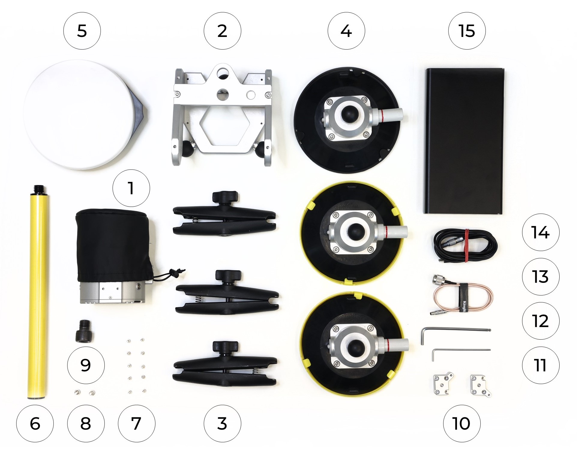
1. TOPODRONE LiDAR - 1 pc. 2. Mobile mount base - 1 pc.. 3. Mobile mount arm - 3 pc. 4. Mobile mount suction cup - 3 pc. 5. GNSS antenna - 1 pc. 6. Pole (30 cm) - 1 pc. 7. M3x10 screw - 10 pc. 8. М5х10 screw - 2 pc. |
9. 5/8" - 11 UNC x 3/4" screw - 1 pc. 10. Mobile mount spacer - 2 pc. 11. Hex 2.5 screwdriver - 1 pc. 12. Hex 4 screwdriver - 1 pc. 13. Antenna cable - 1 pc. 14. LEMO 6 PIN - USB Type-C power cable - 1 pc. 15. Power Bank - 1 pc. |
It is strongly recommended to use a TOPODRONE LiDAR protective soft cover for to avoid the risk of damaging the laser scanning lens! For better clarity, in the photos shown, the TOPODRONE TOPODRONE LiDAR is shown without the case.
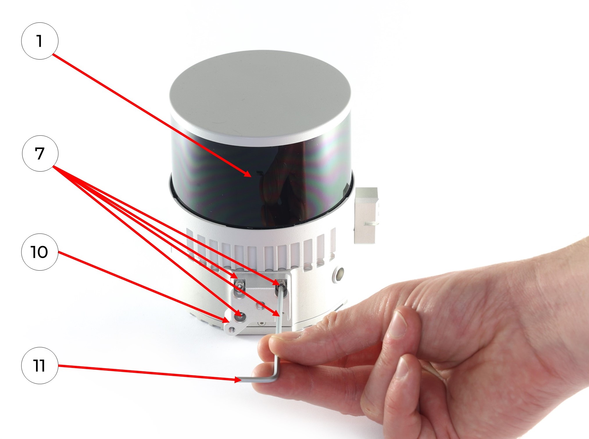
1. Install the two mobile mount spacers (10) on the TOPODRONE LiDAR (1) with 8 M3x10 (7) screws using a Hex 2.5 (11) screwdriver as shown in the photo:
|
|
|
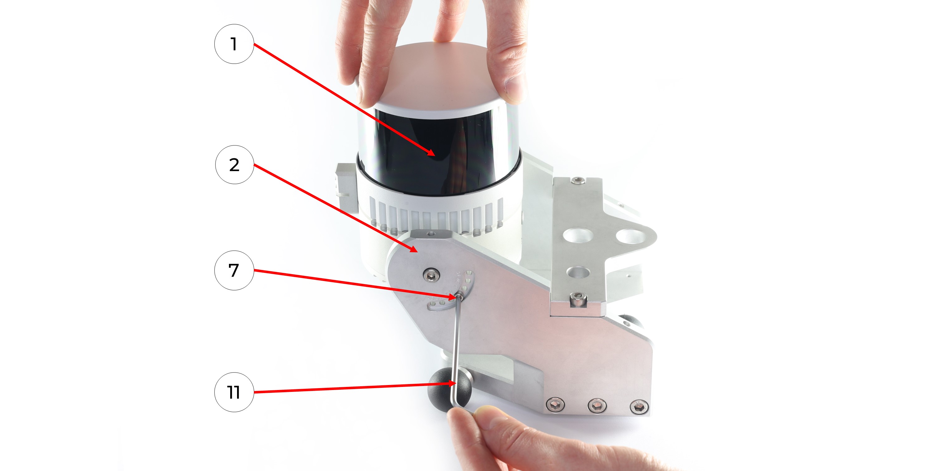
2. Install TOPODRONE LiDAR (1) on the mobile mount base (2) with two M5x10 screws (8) using a Hex 4 (11) screwdriver as it shown at the photo below. Be extremely careful at this step!
Hold the TOPODRONE LiDAR (1) so that it does not fall and proceed to step 3. Use the cover to protect the lens! It is especially important in this step!
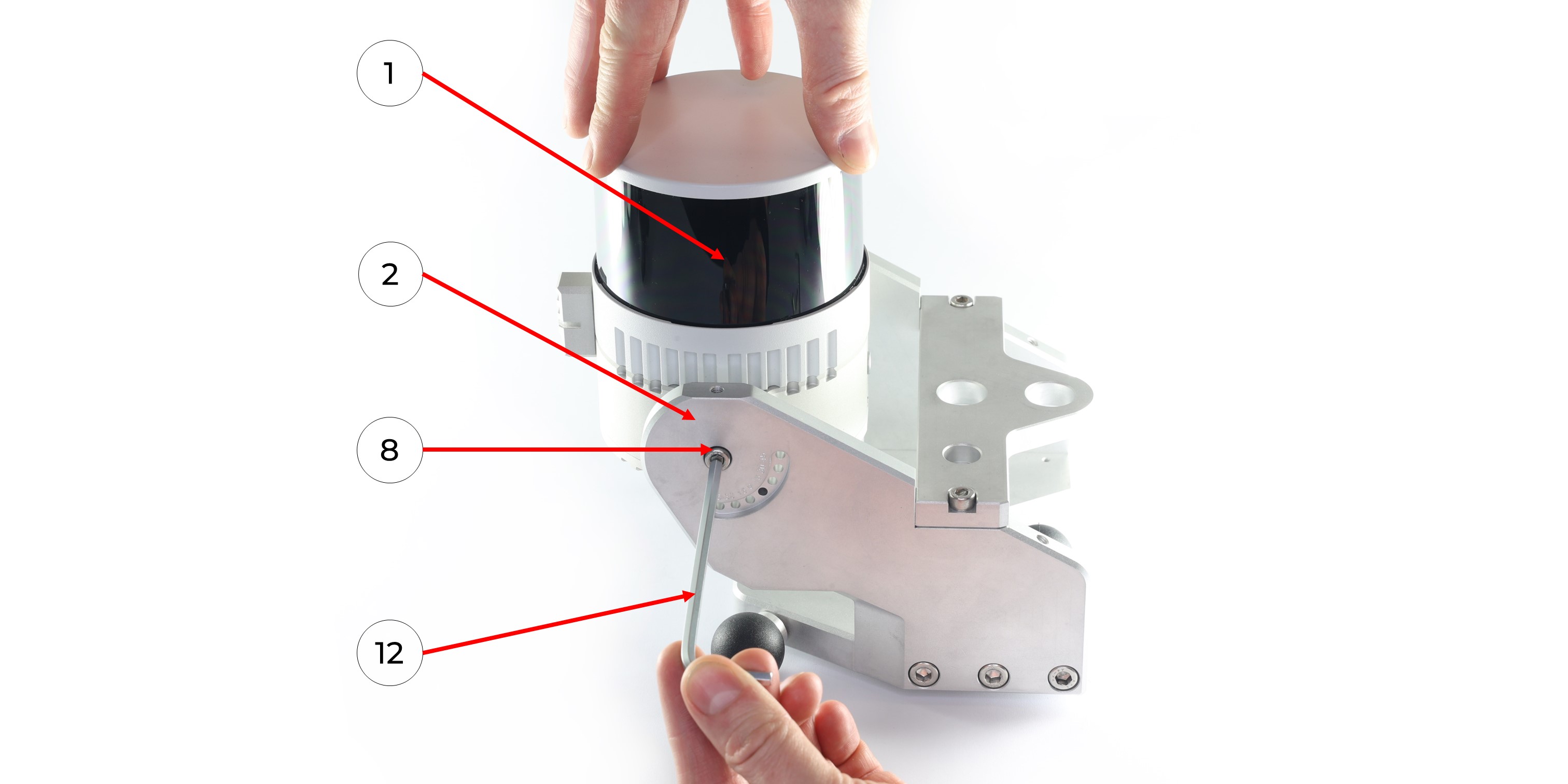 3. Set the TOPODRONE LiDAR (1) at the required angle on the main part of the mobile mount (2) and fix the position with two M3x10 screws (7) using a Hex 2.5 screwdriver (11).
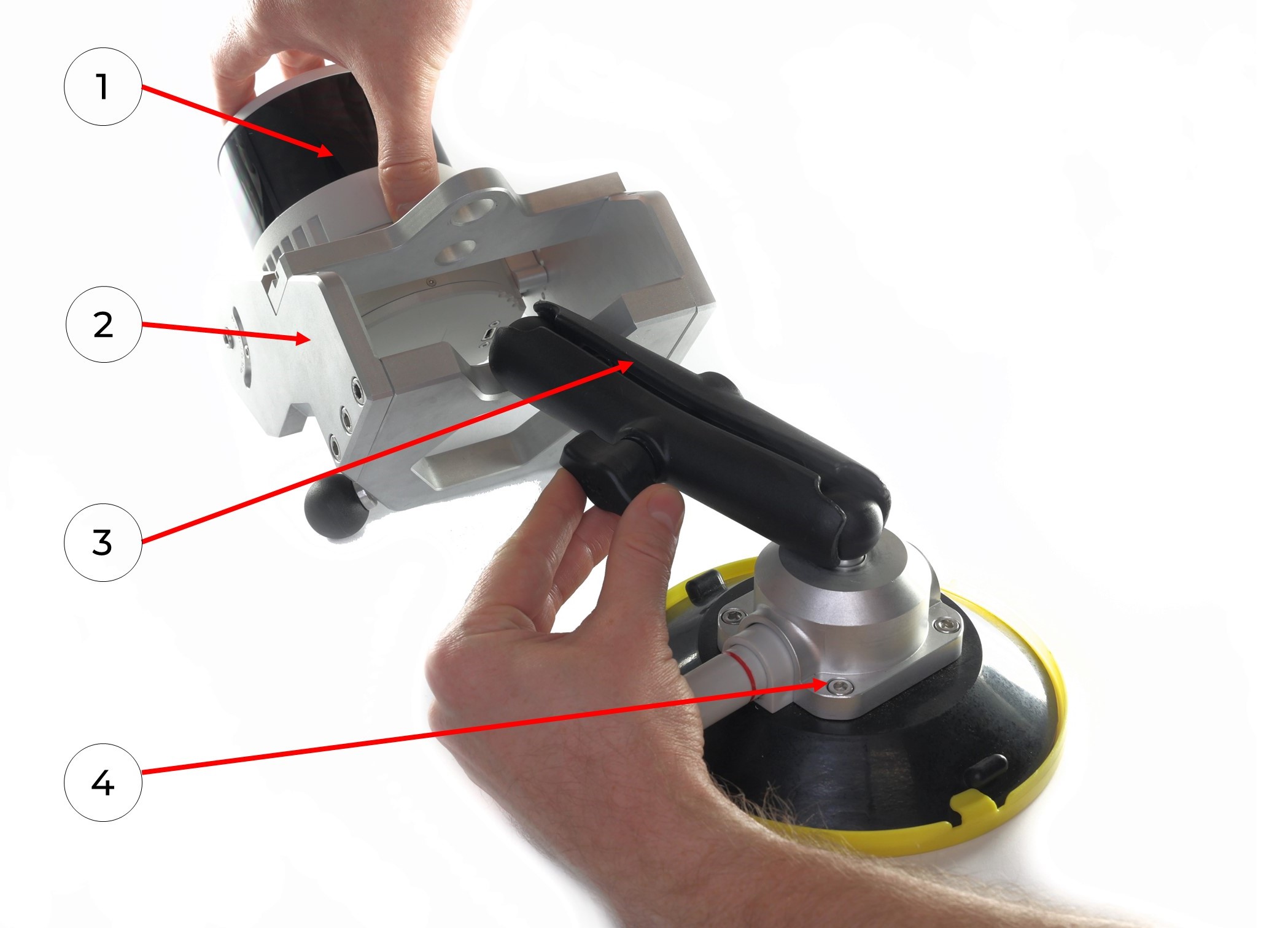
4. Connect the mobile mount arm (3) to the suction cup swivel mechanism (4), repeat with all parts.
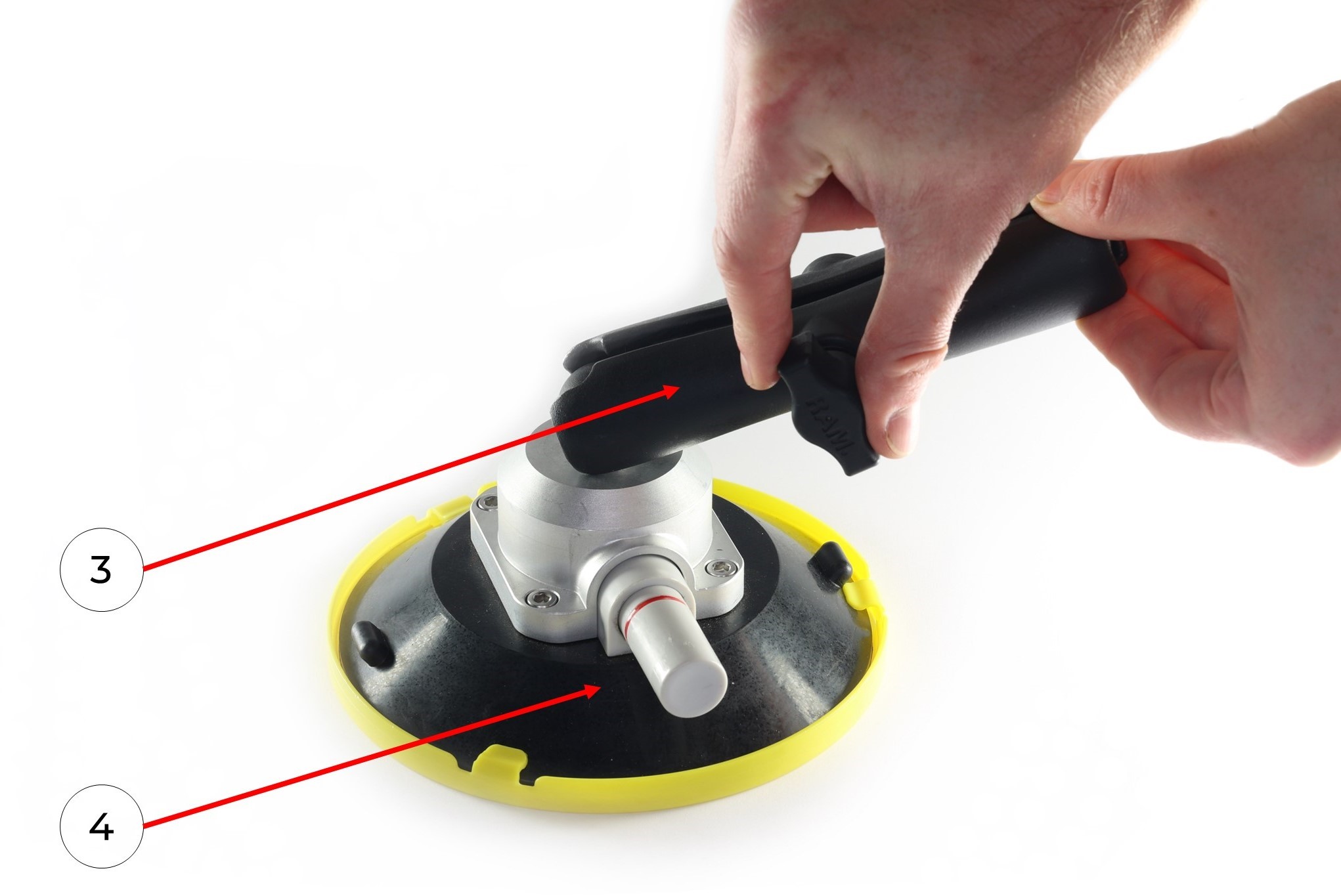
5. Connect the mobile mount arm (3) with the other side to the hinge mechanism of the mobile mount base (2). If necessary, manually loosen or tighten the thumbscrew. Once the hinge mechanisms are in alignment, manually tighten the thumbscrew. Repeat with all parts.
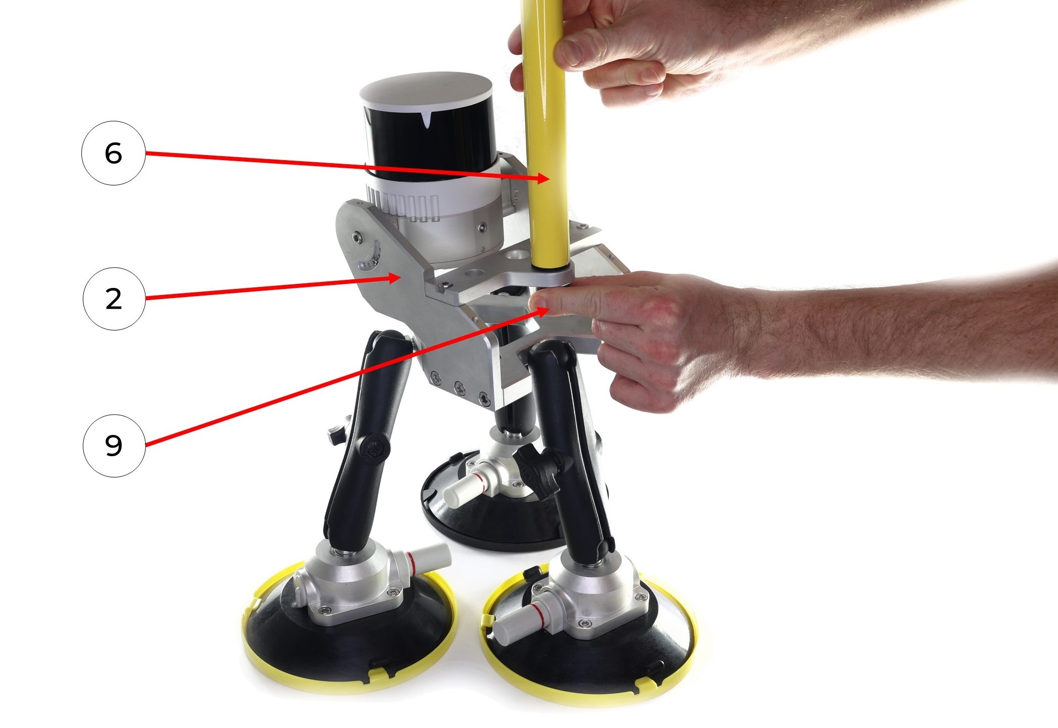
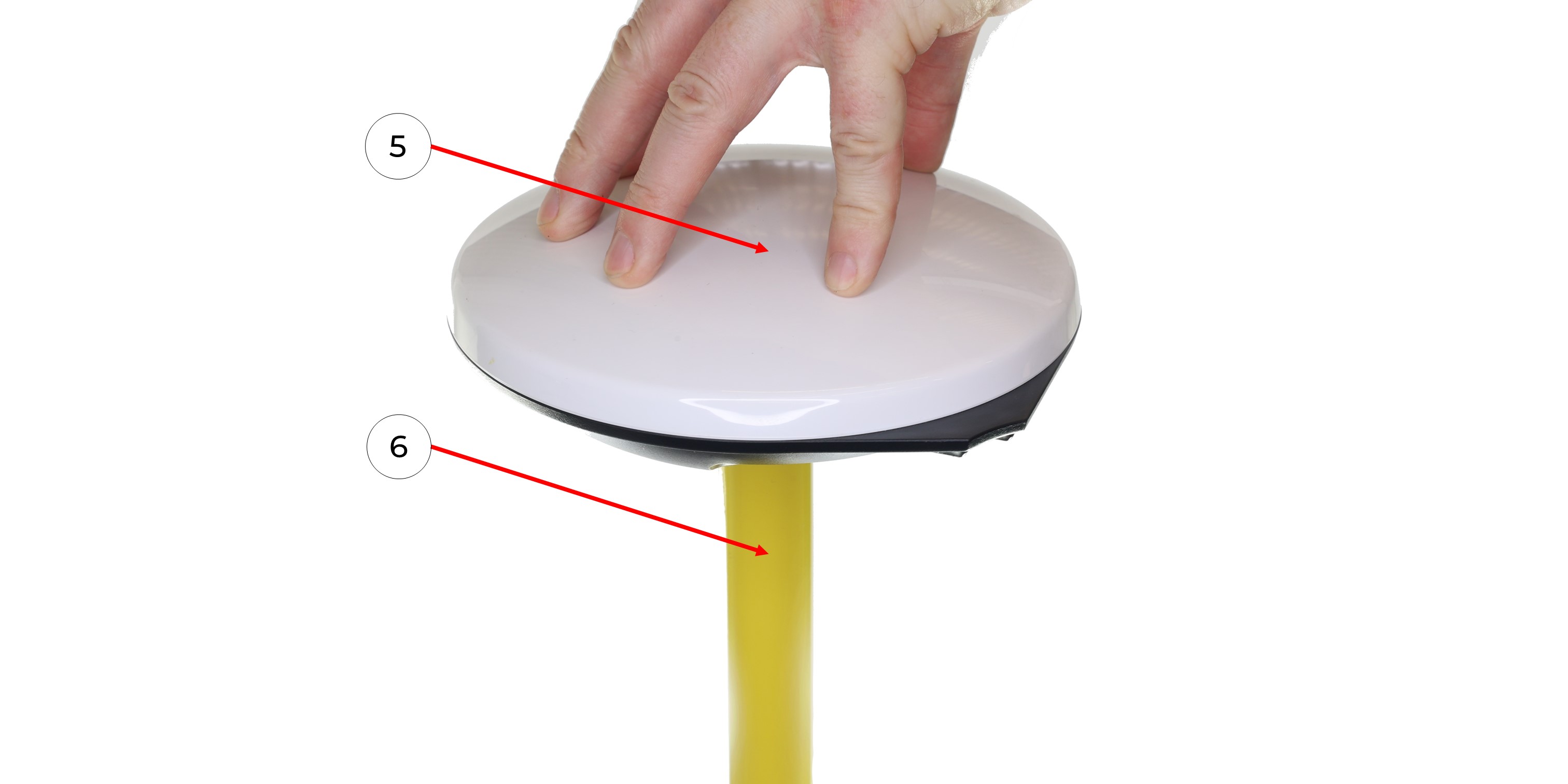
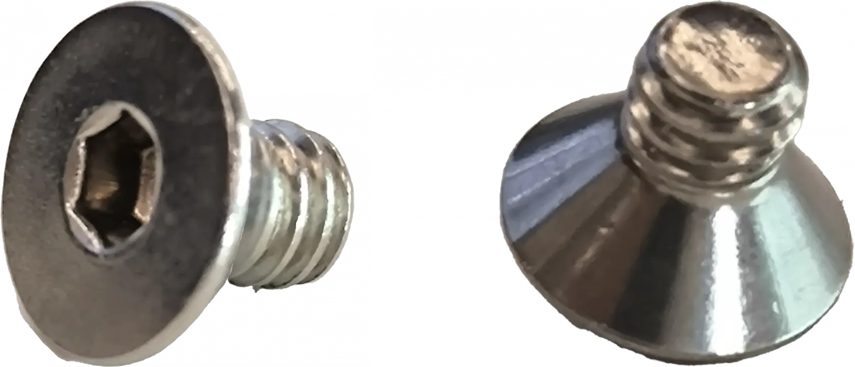
6. Install the pole (6) to the mobile mount base (1). Manually tighten the 5/8" - 11 UNC x 3/4" screw (9).
7. Screw the GNSS antenna (5) onto the pole (6).
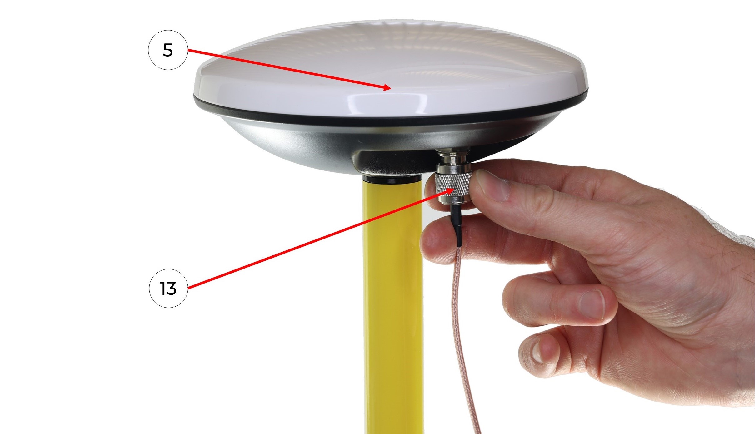
8. Connect the GNSS cable (13) to the GNSS antenna (5), taking care not to bend it.
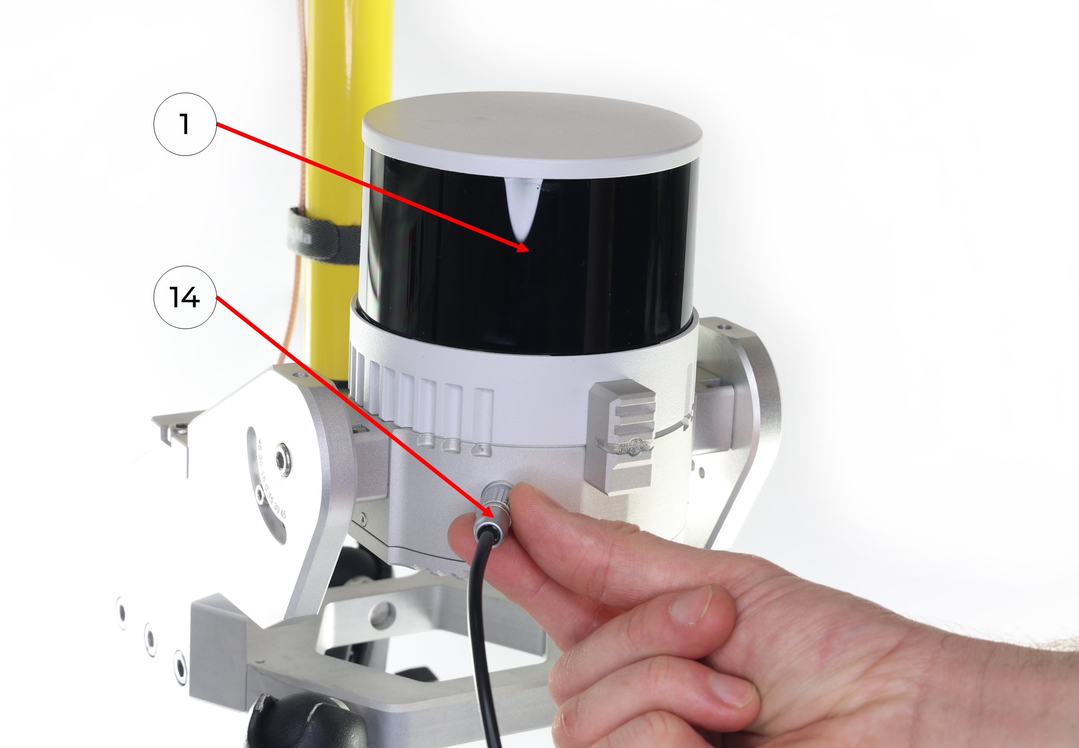
9. Connect the antenna cable with the LEMO connector (13) to the TOPODRONE LiDAR (1) it clicks into place.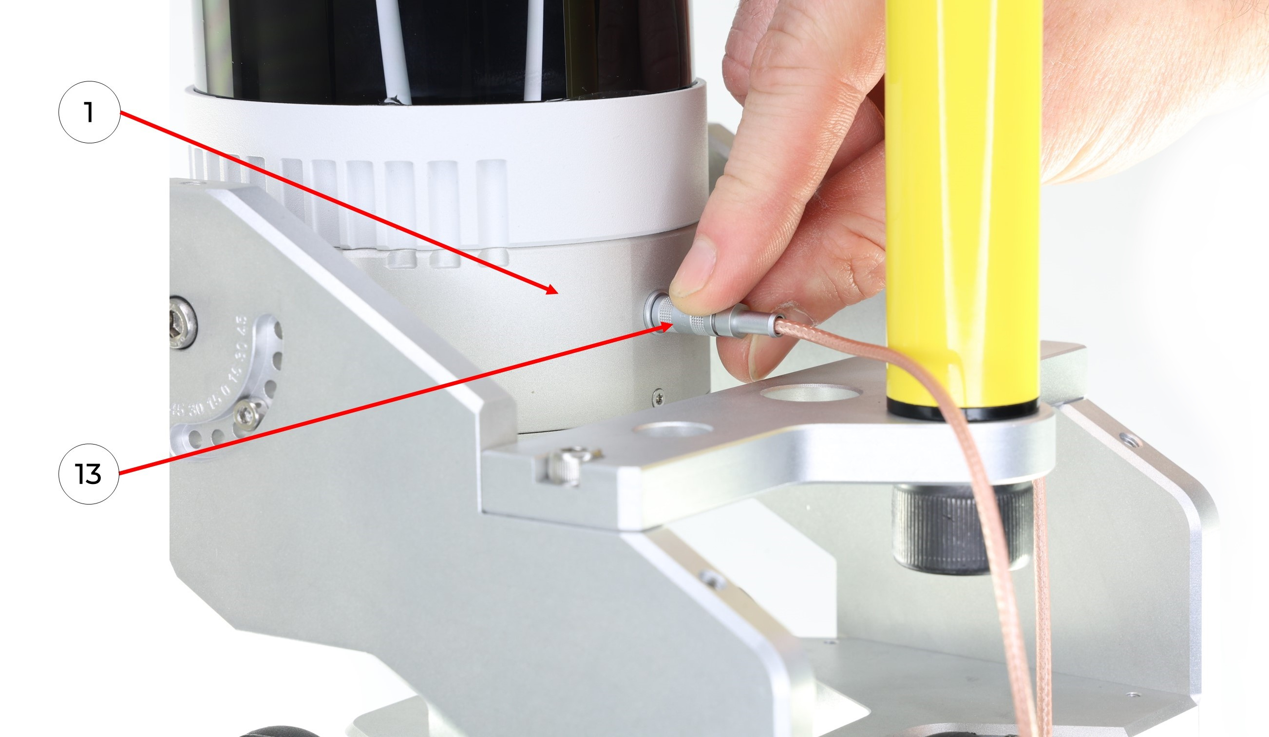
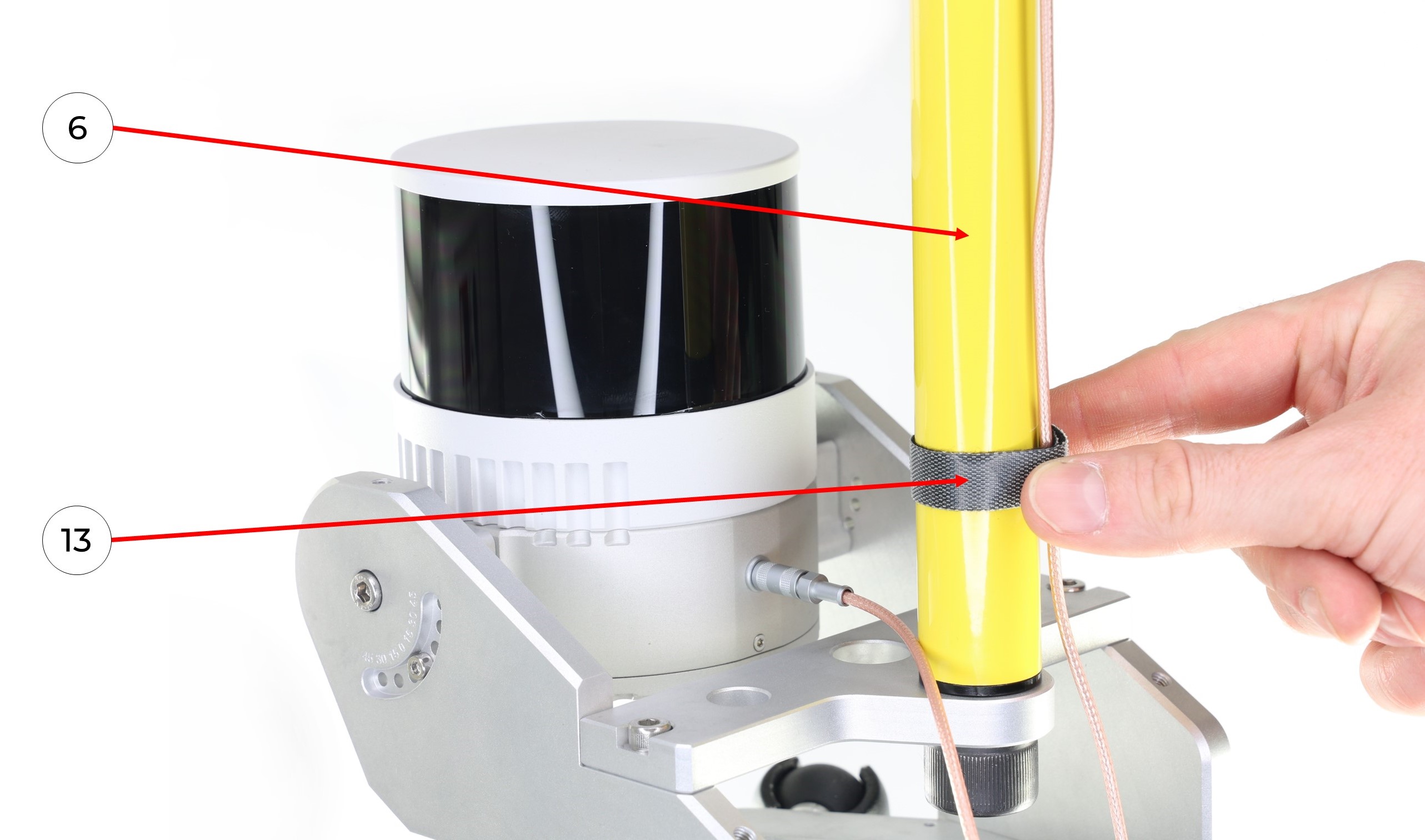
10. It is recommended to fix the antenna cable in the area of the pole (6) with a GNSS cable velcro (13) as shown in the photo.
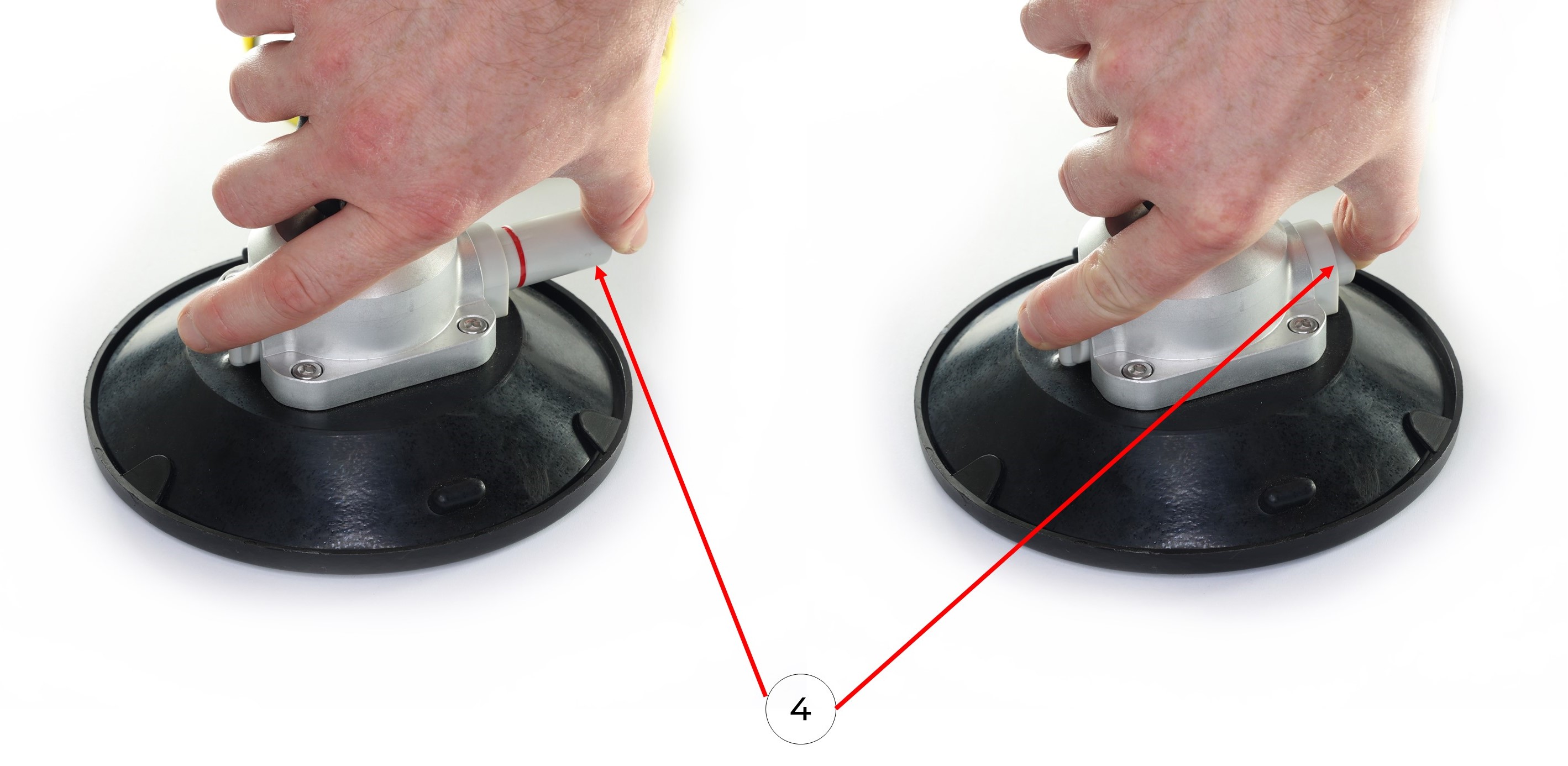
11. Clean the surface of a vehicle with wet and dry wipes. Remove the protective caps from the suction cups (4). Install the mobile mount on the car with the suction cups (4) using the pump. It is necessary to pump the pump until the pump stops pumping out air and the suction cup is completely glued to the surface. The photos below show the process of pumping the air out of the suction cups without removing the suction cup caps.
 12. Connect the LEMO 6-Pin connector of power cable (14) to the TOPODRONE LiDAR (1), it clicks into place.
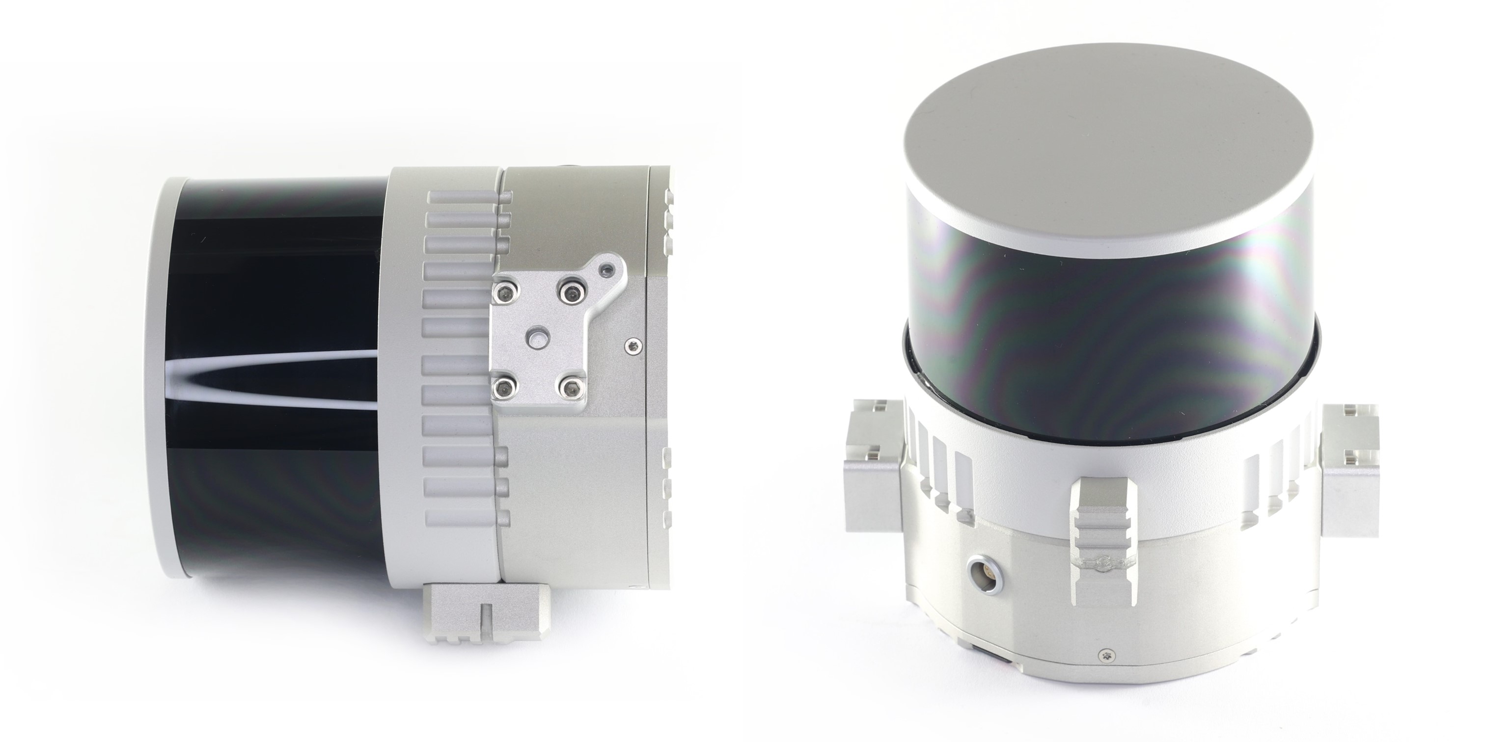
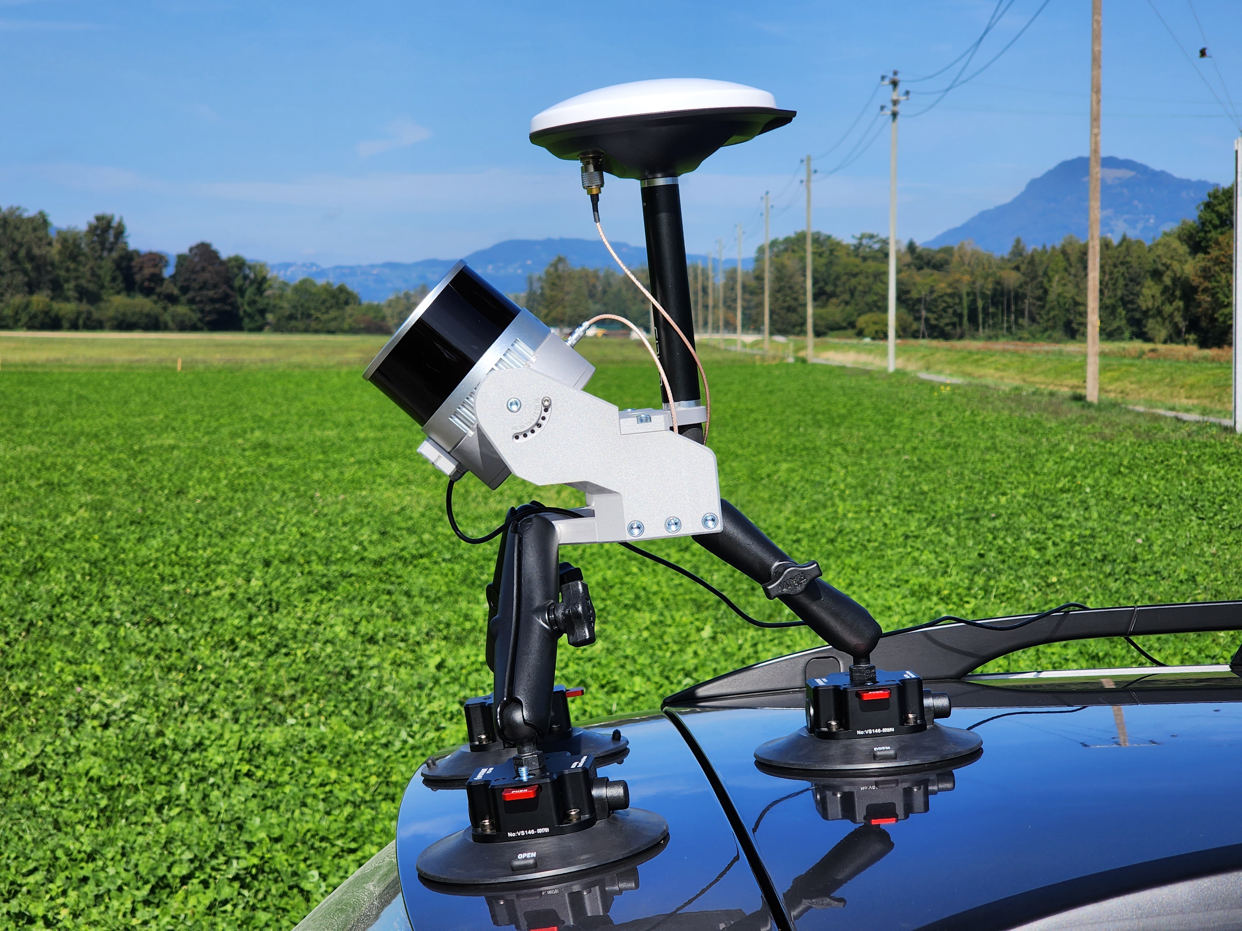
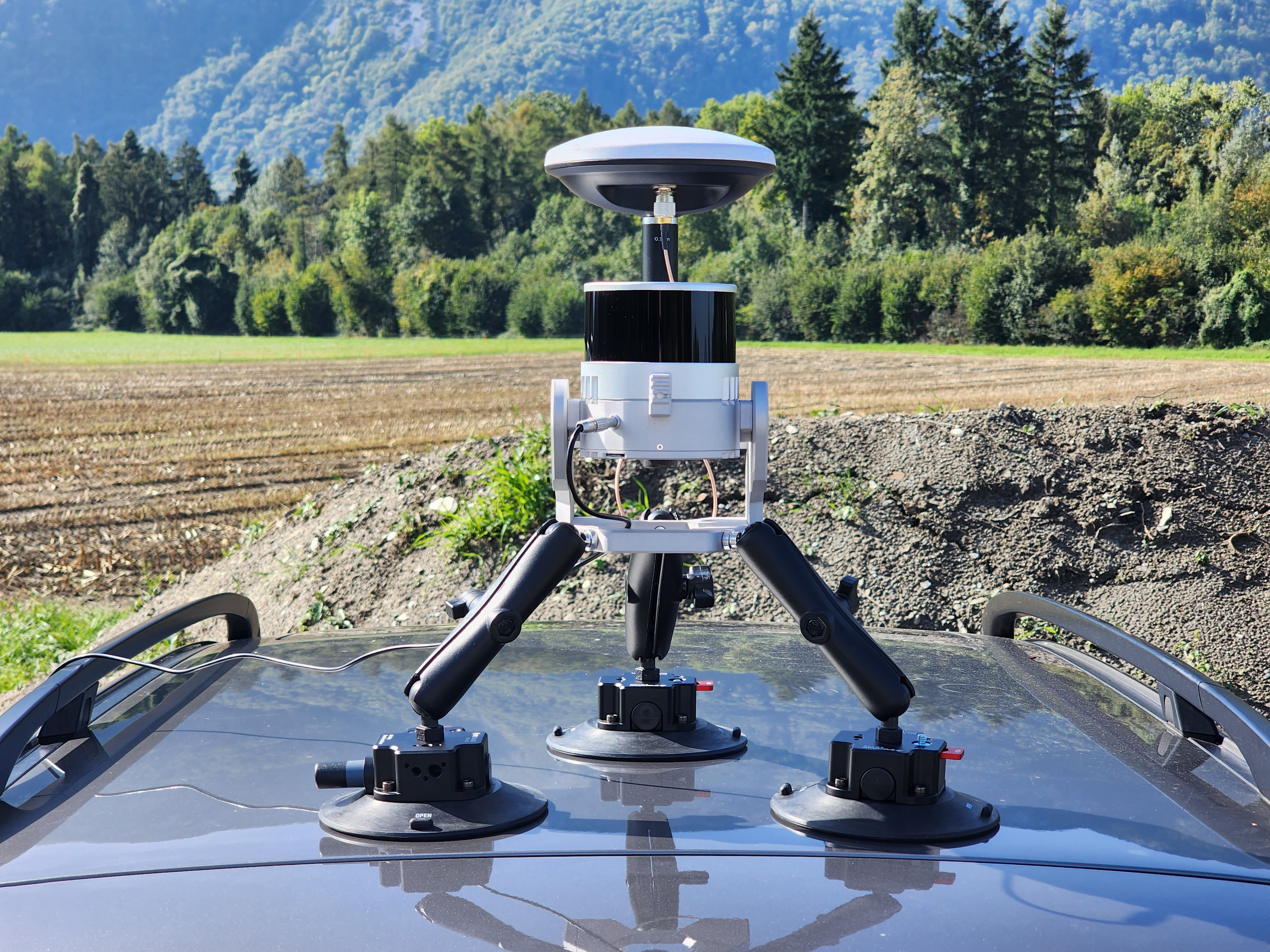
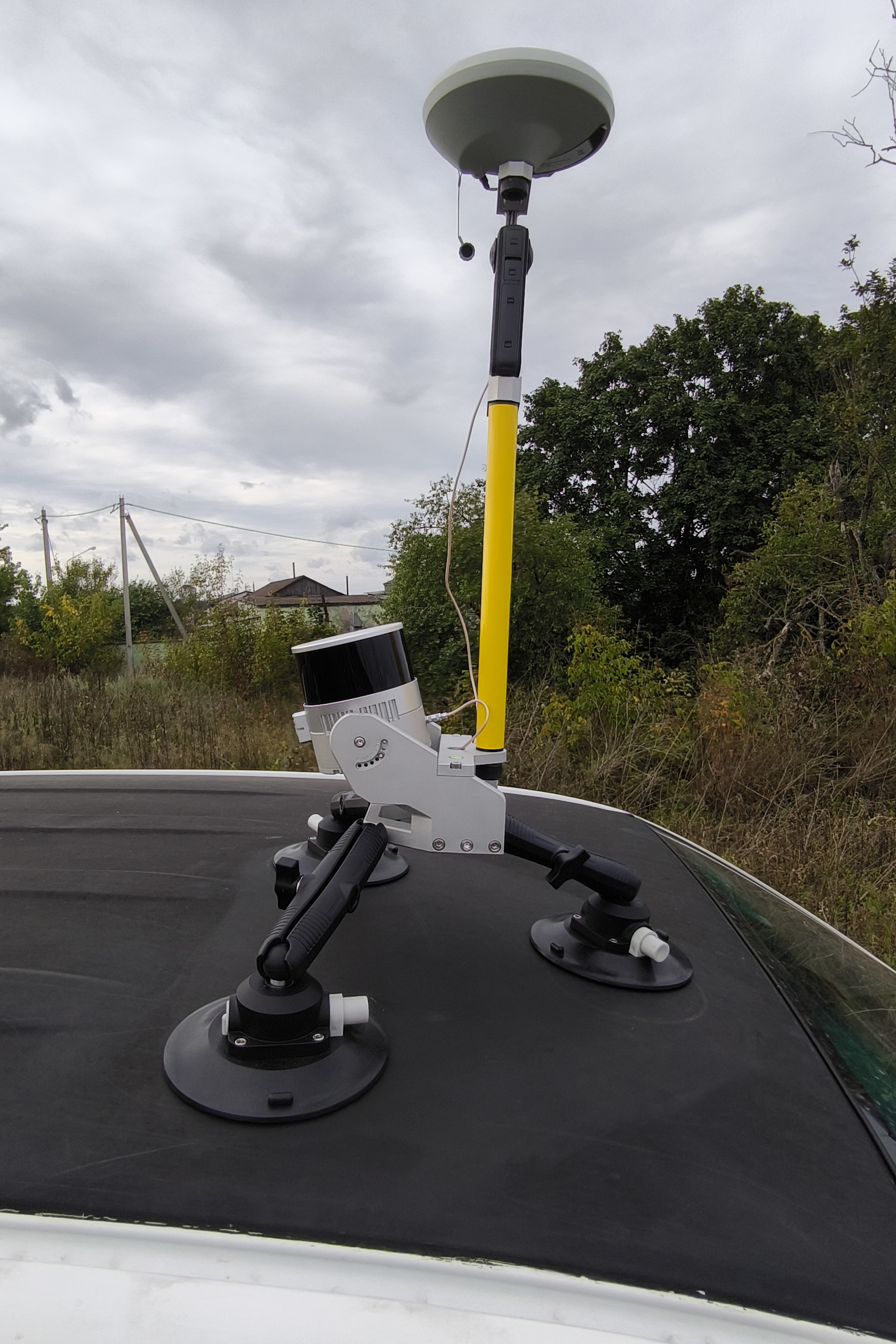
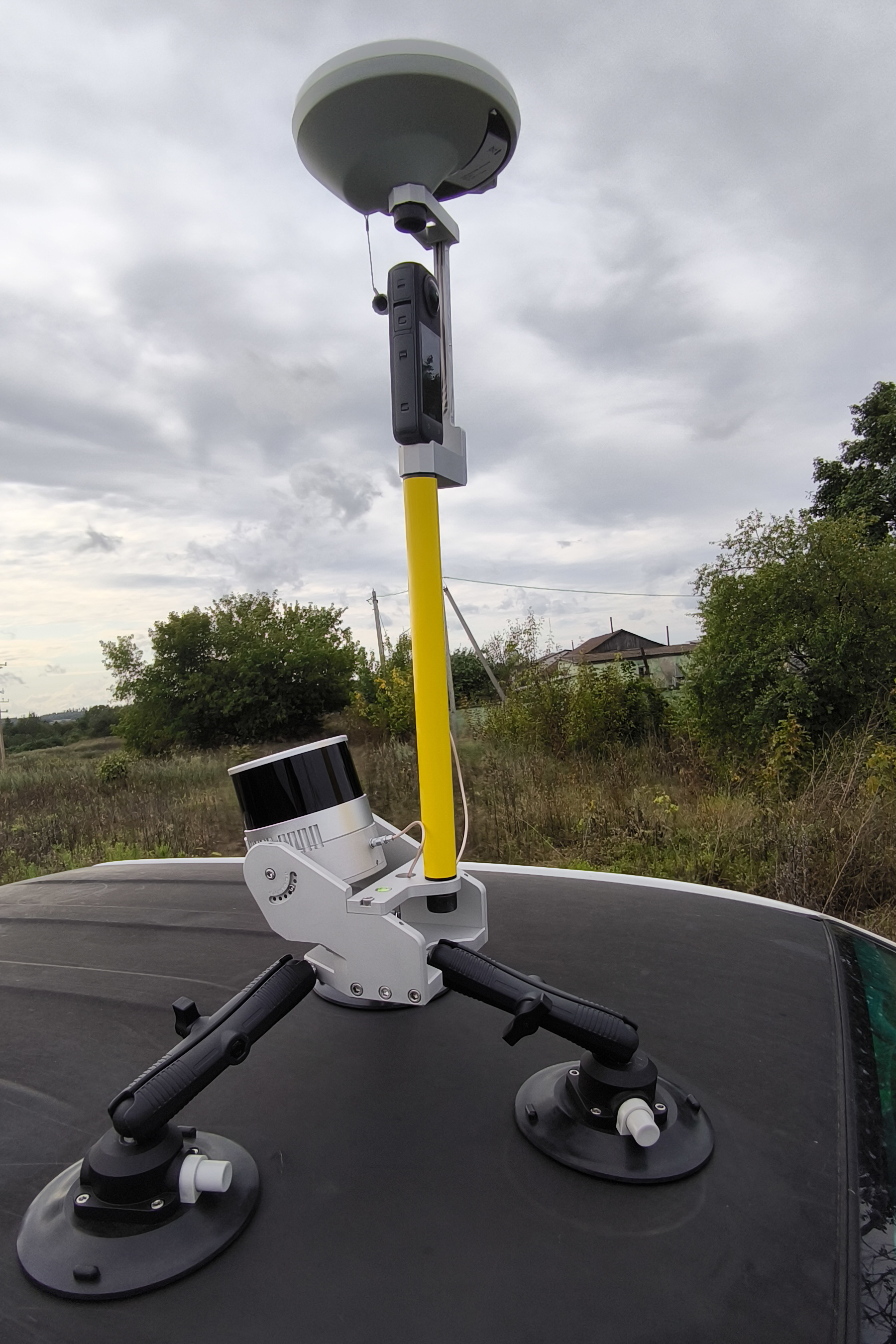
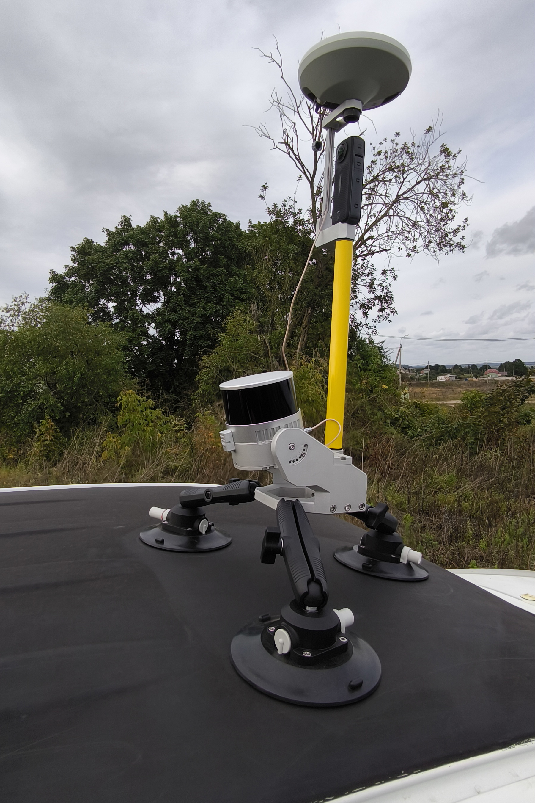
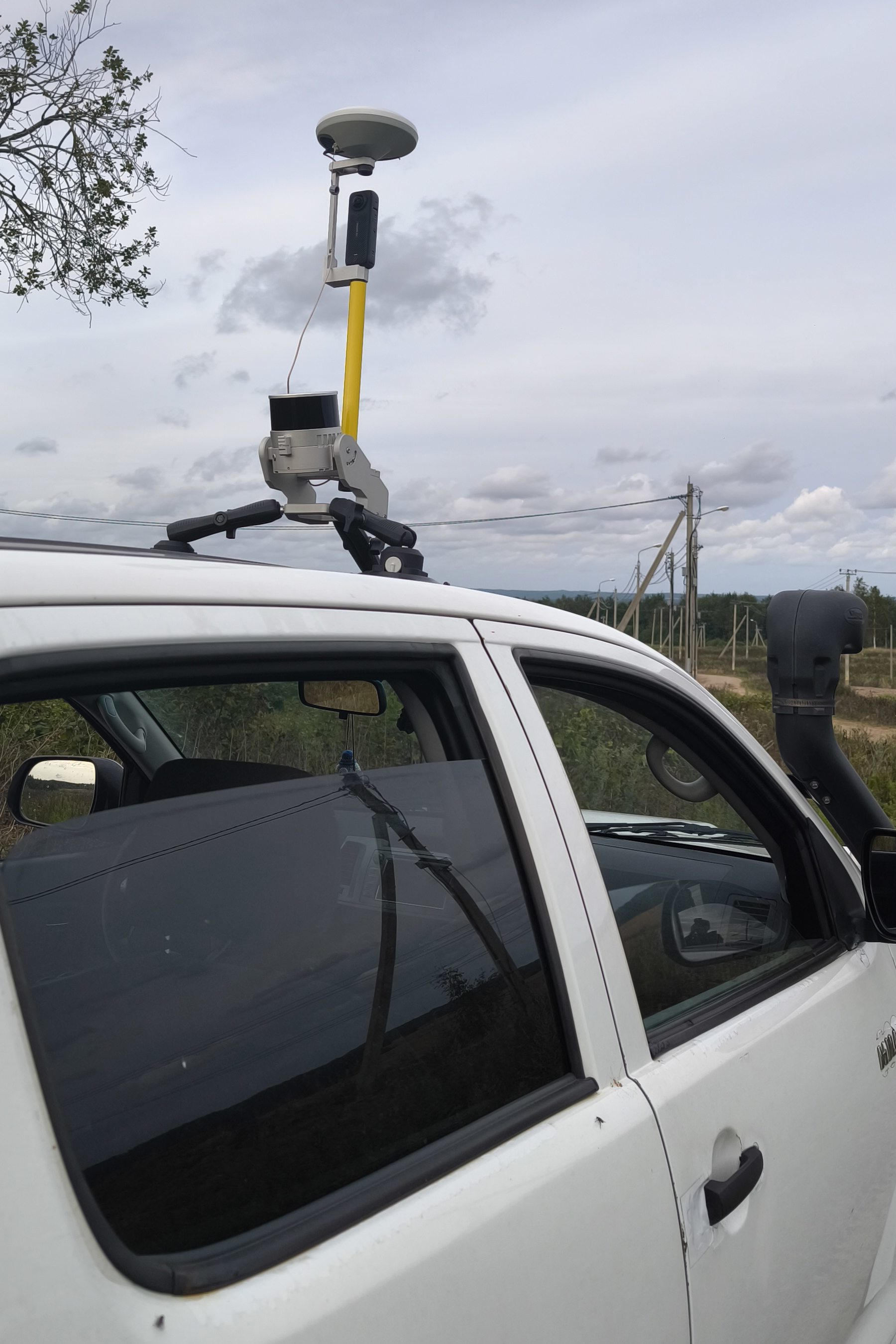
13. If necessary, use the beam wrenches to adjust the position of the mobile mount on the vehicle so that it is level. The photos below show how to mount the TOPODRONE 100+ laser scanner on the vehicle at 30 and 0 degrees respectively.
Note: in the photos below, a non-standard 20 cm long milestone is used, which is different from the one supplied.
 |
|
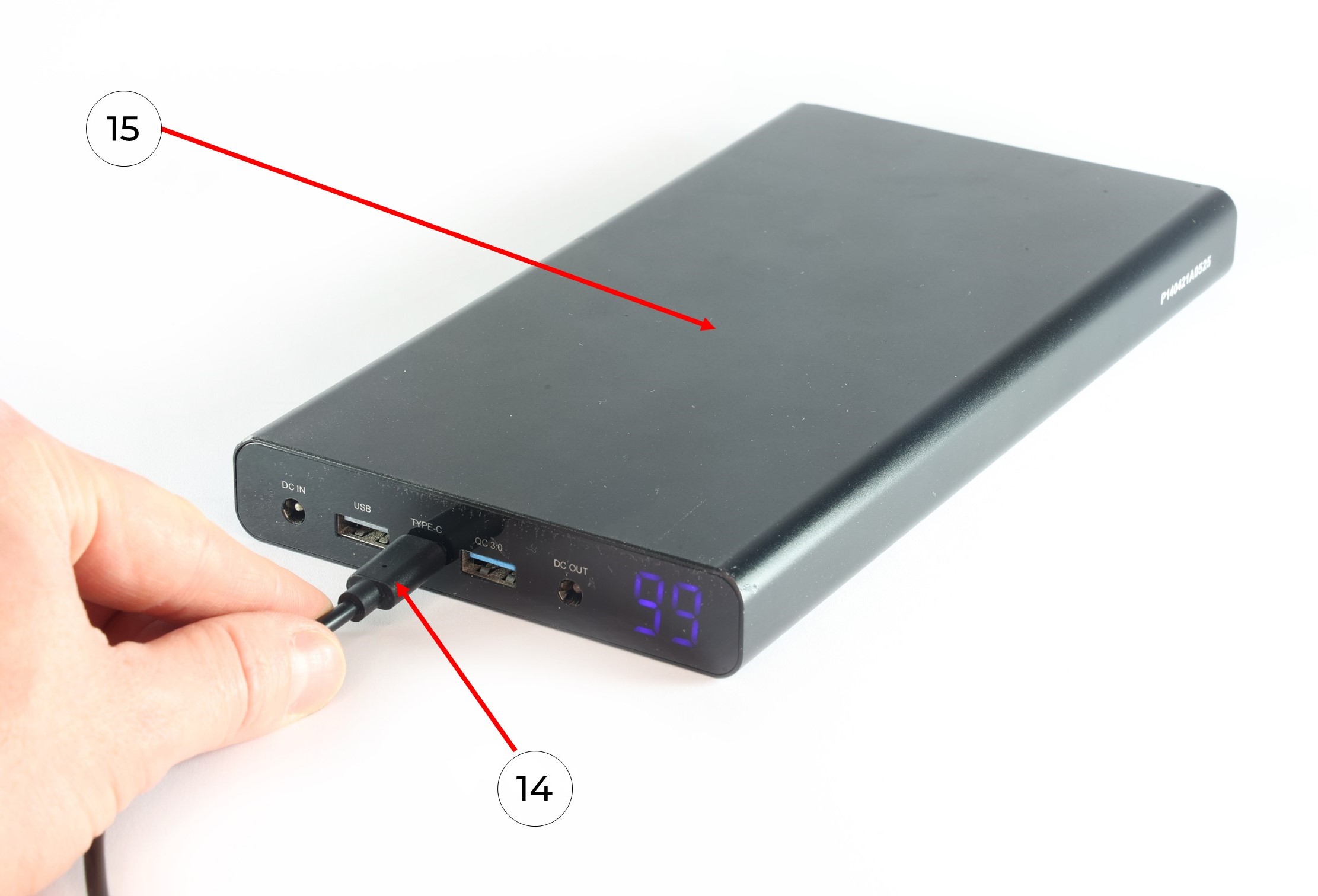
14. Connect the USB-C port oft the power cable (14) to the Power Bank (15) and apply power. Wait for the TOPODRONE LiDAR to initialize.
It is recommended to check the grip of the suction cups every hour, especially at sub-zero temperatures!
Do not install the suction cups on dirty, dusty surfaces, as well as on joints of planes and parts with seams and gaps.
Assembly of the Mobile Scanning Kit
Additional equipment required for kit assembly:
-
Insta 360 X4 camera;
-
microSD memory card for the Insta 360 X4 camera (128 GB recommended);
-
Camera mounting bracket for Insta 360 X4;
-
Extended antenna cable (70-80 cm);
-
Mounting screw for securing the GNSS antenna;
-
1/4-inch hex socket flat head screw for attaching the camera to the bracket.
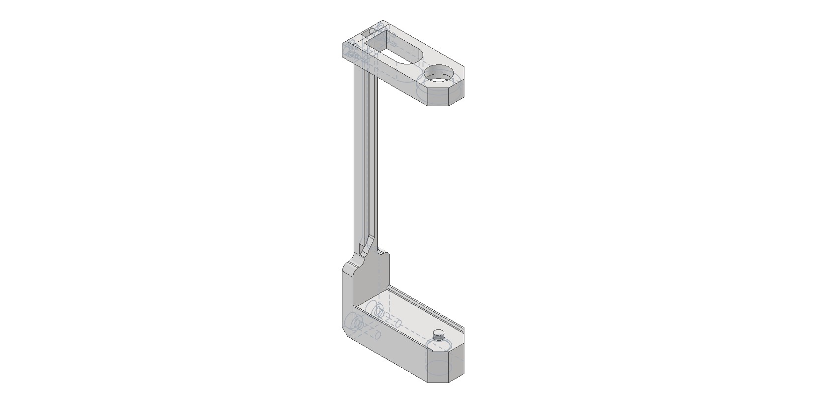
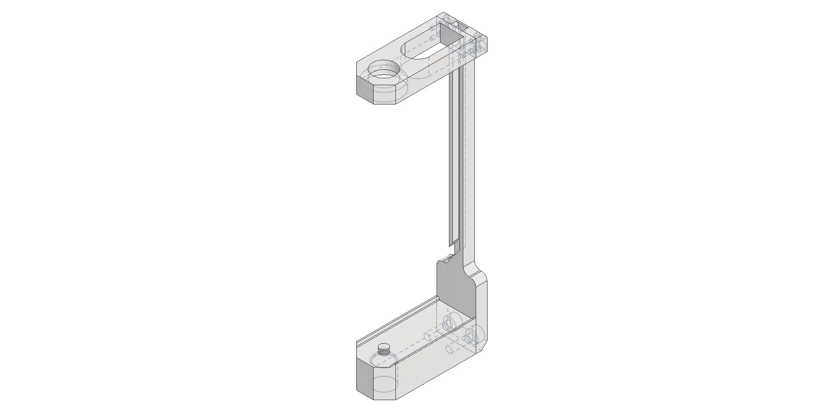
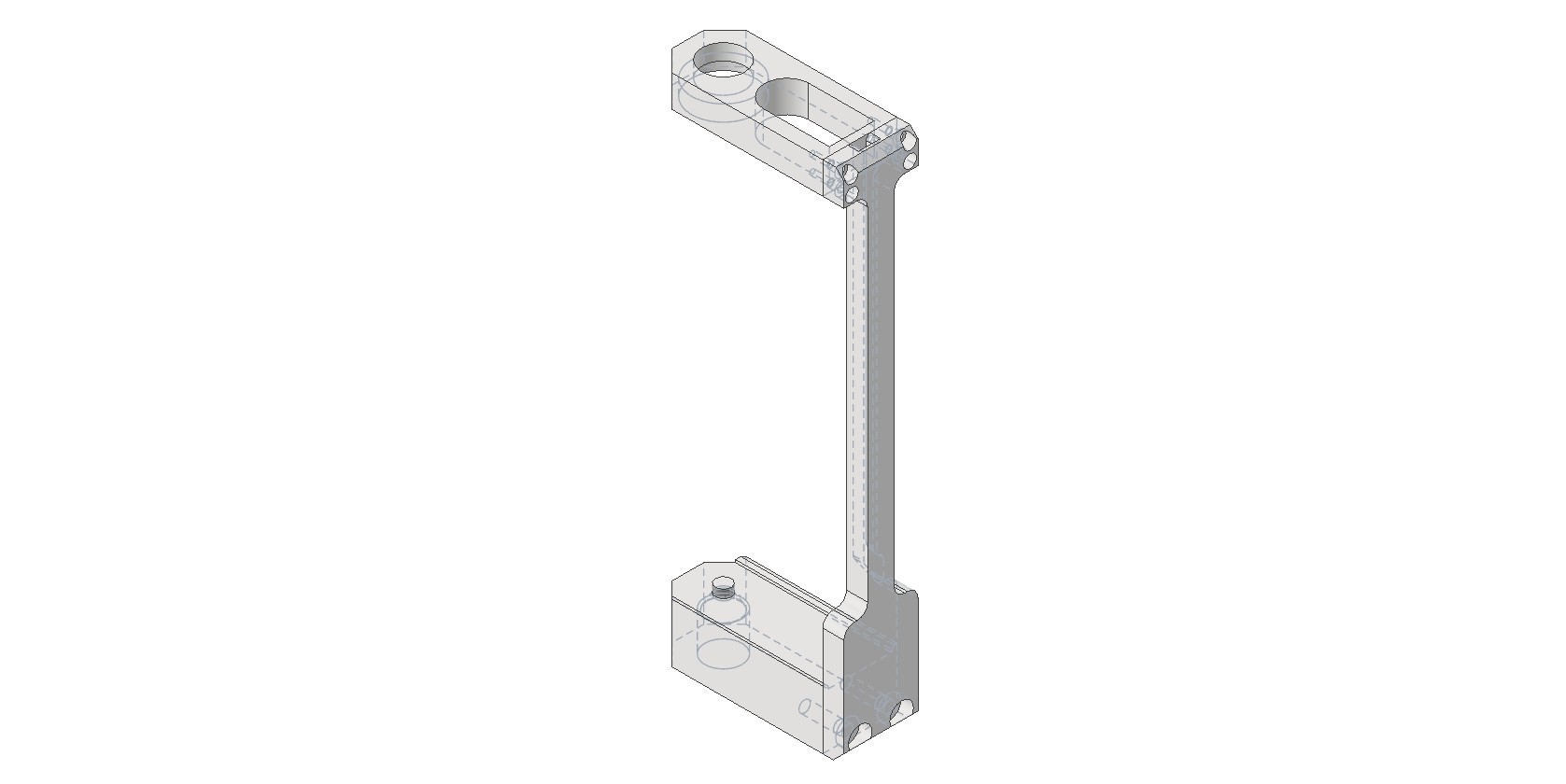
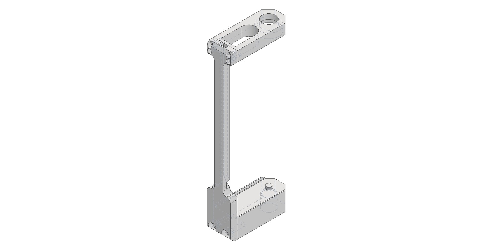
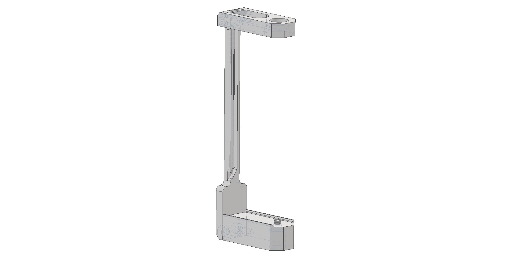
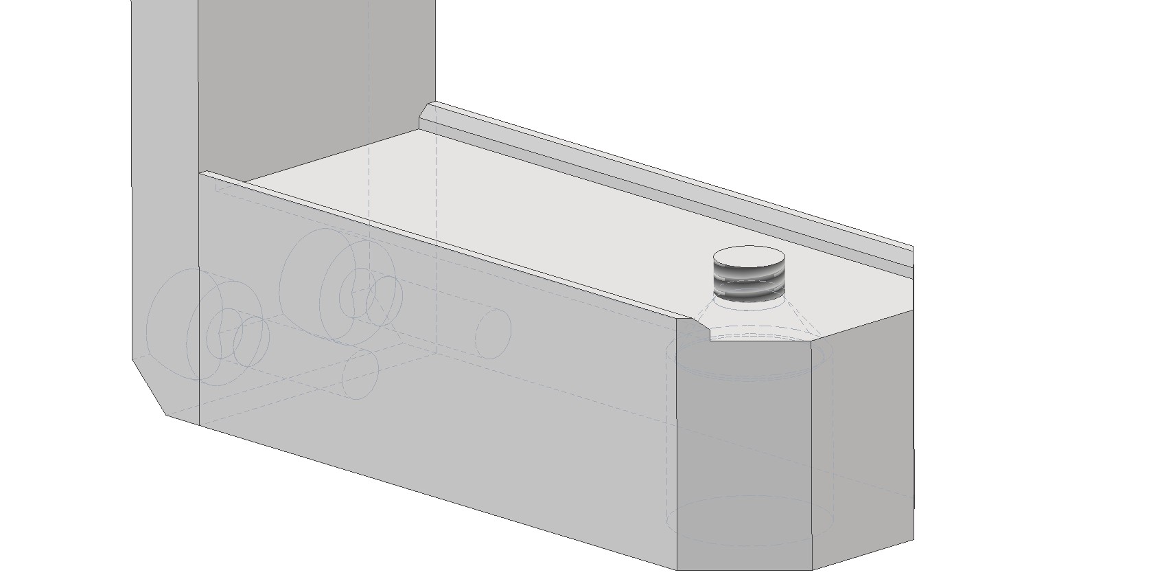
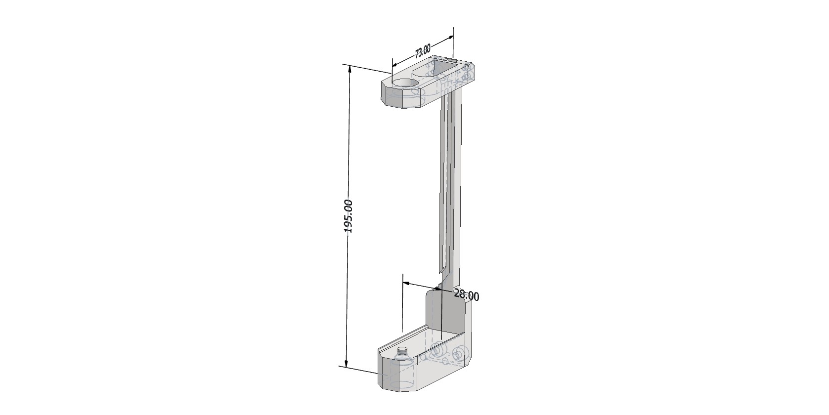
Camera Mounting Bracket Appearance
The bracket dimensions are 195×73×28 mm. The top hole is designed for the GNSS antenna mounting screw. The bottom hole is for the 1/4-inch hex socket flat head screw used to attach the camera to the bracket. The bracket is then screwed onto the pole.
Assembly Procedure for the Insta 360 X4 Camera Shooting Kit
The kit is assembled using the standard procedure, with an additional step for camera installation. Sequence of operations:
1. Install the camera into the bracket.
- Secure the Insta 360 X4 camera in the dedicated bracket using the 1/4-inch hex socket flat head screw.
- Camera orientation: Position the camera so that the optical axis of the lens located on the display side is aligned with the direction of travel of the scanning system.
2. Mount the bracket on the pole.
- Screw the bracket with the attached camera onto the geodetic pole.
3. Install the GNSS antenna.
- Place the geodetic GNSS antenna on top of the bracket and secure it with the standard mounting screw.
- Connect the antenna cable.
Insta 360 X4 Camera Settings
Before installing the camera into the bracket and starting data collection, remove all additional accessories from the camera, such as protective cases and lens covers. The presence of any foreign objects on the camera leads to data defects and is not permitted.
The camera configuration parameters are provided in the table below.
| Setting | Setting value | Setting value |
| Data acquiring mode | Video 360° | Timelapse 360° |
| Scene selection mode | MegaView | - |
| Resolution | 5.7К | 5.7К |
| Frame Rate | 30 | 30 |
| Interval | - | 0.5 |
Data Collection Methodology
The field work procedure is as follows:
-
Assemble the mobile kit with the TOPODRONE laser scanner and camera.
-
Install the mobile kit on the vehicle.
-
Turn on the laser scanner, wait for data recording to begin, then turn on the camera and start video recording.
-
Perform a calibration maneuver and proceed with data collection in the survey area.
-
After completing the survey route, turn off the scanner and the camera.
You can learn more about the mobile laser scanning methodology on the page: Mobile Laser Scanning (MLS)
No Comments