
Airborne Laser Scanning (ALS)
The TOPODRONE LiDAR is designed to perform airborne laser scanning (ALS). To perform this procedure, you will need a drone that supports the correct installation of the TOPODRONE LiDAR and is capable of following a planned flight path. One such drone, for example, is the DJI M300/350 RTK.
TOPODRONE LiDAR ALS rules:
1. Neighboring spans (hereinafter for simplification - scans) should have a lateral overlap of 30% or more. 2.
2. Scans should be parallel to each other
3. The drone must follow neighboring scans in forward and reverse directions
4. The movement speed of the drone with the TOPODRONE LiDAR on the main section of the ALS should be constant
5. The distance from the TOPODRONE LiDAR to the ground surface shall be constant
6. To obtain correct ALS data, it is recommended to take at least two scans
7. Use original propellers to reduce vibration
8. Do not fly in squall winds or during precipitation to reduce noise
9. After initializing the TOPODRONE LiDAR and taking off, perform a calibration maneuver before the main ALS section of each flight
10. If the flight takes more than 30 minutes, it is recommended to perform the calibration maneuver again when the session time reaches 30 minutes after turning on the TOPODRONE LiDAR.
ALS and the terrain elevation:
At insignificant height differences at the ALS location (up to 10 meters) it is allowed to fly the drone with TOPODRONE LiDAR at a fixed altitude (AMSL). The altitude of the drone flight is set relative to the altitude of the takeoff point. Accordingly, for the main part of the flight, almost any software can be used, allowing to set the flight on a circle (to perform the calibration maneuver), as well as to set the distance between parallel passages.
If altitude differences at the ALS location (10 meters or more) are exceeded, it is necessary to use software that supports the “elevation envelope” (AGL) function for ALS route planning. The most convenient way to plan such routes is to use UgCS Expert software.
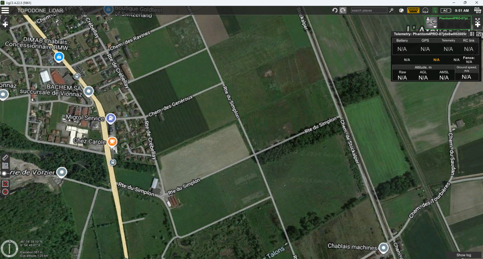
This is an example of UgCS Expert software and DJI M300/M350 RTK:
- Install UgCS Expert software and open it.
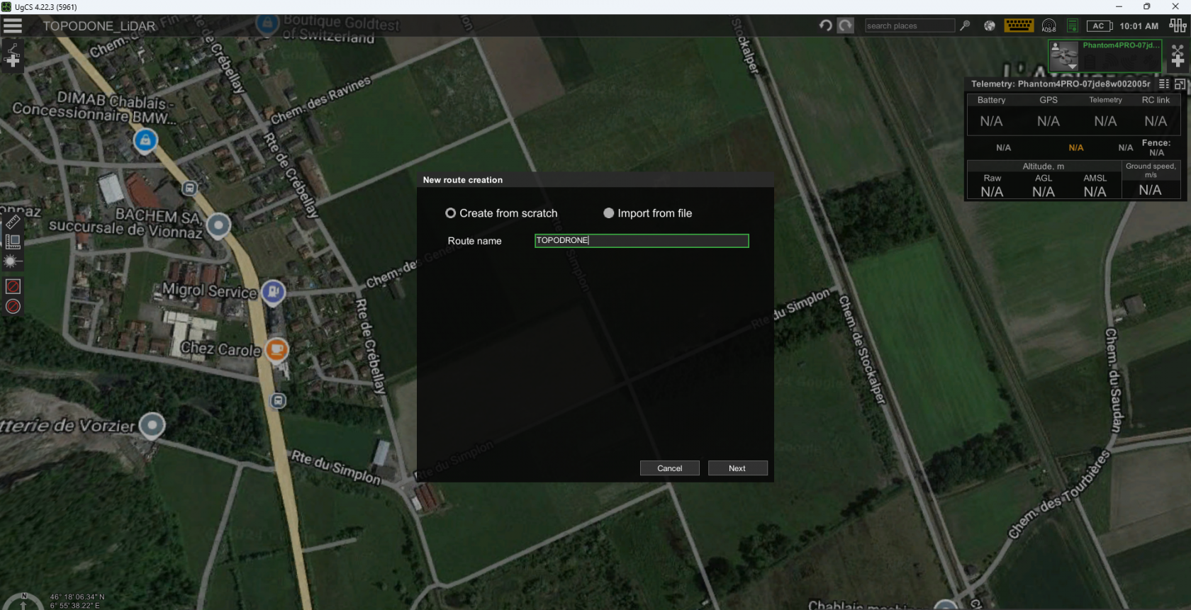
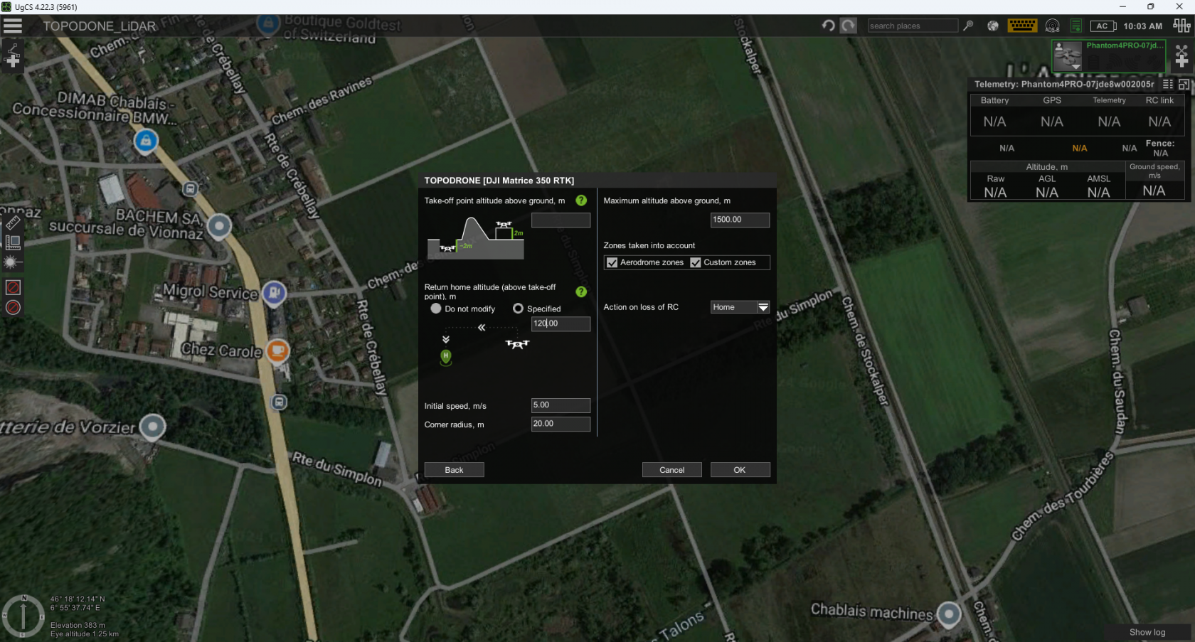
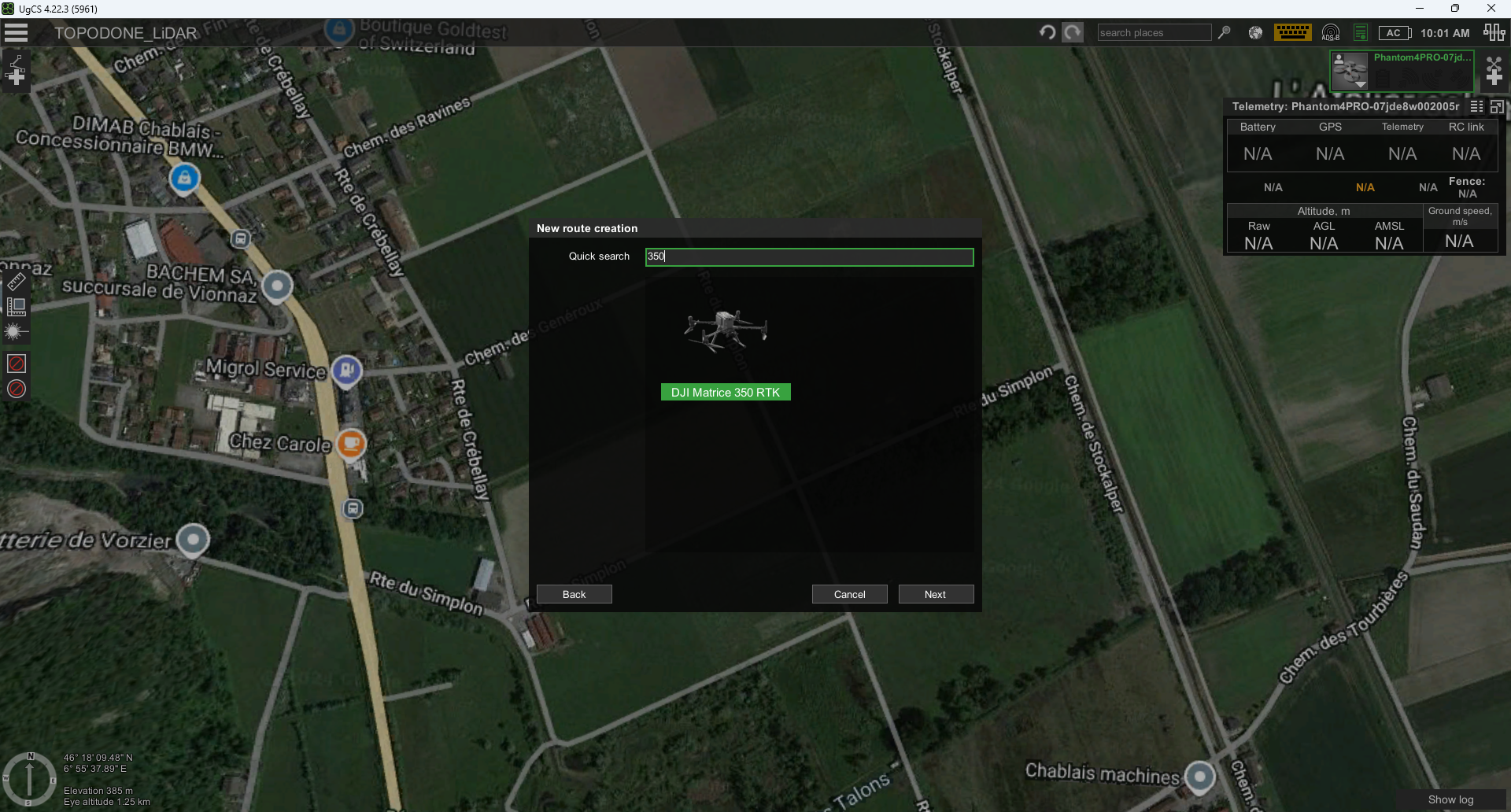
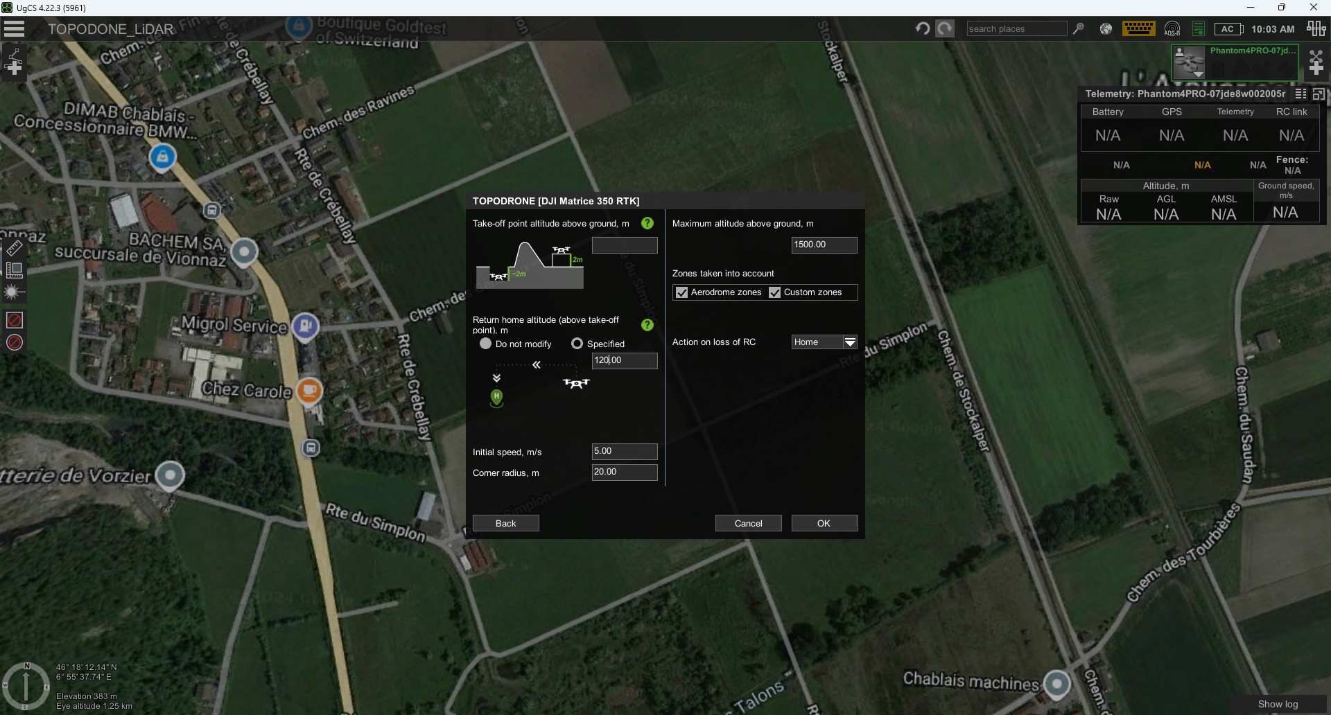
- Create a new mission and create a route for the DJI M300 RTK or DJI M350 RTK drone profile


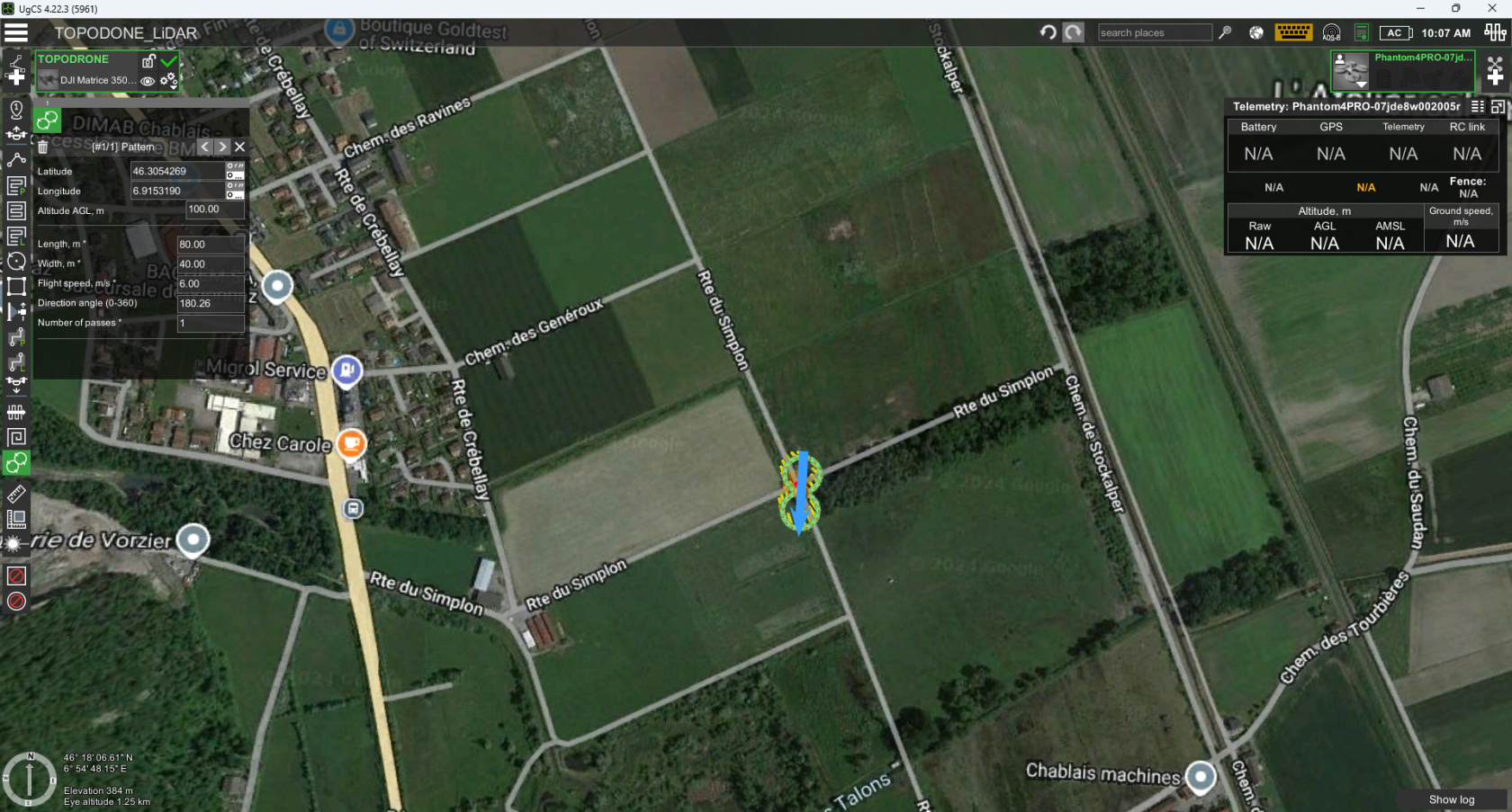
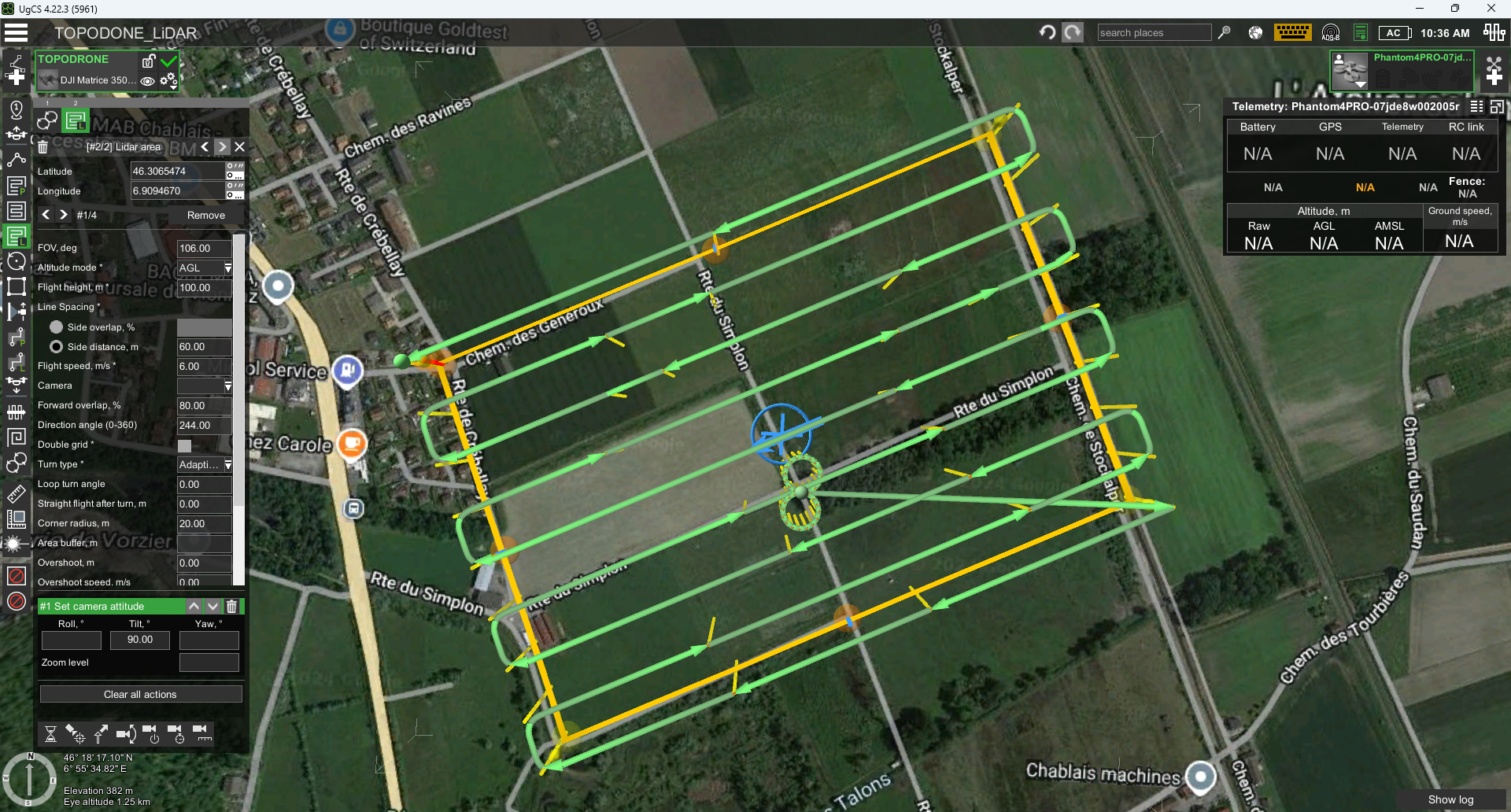
- Using the “Pattern” tool set a calibration maneuver in the form of an infinity sign as close as it possible to a route start point
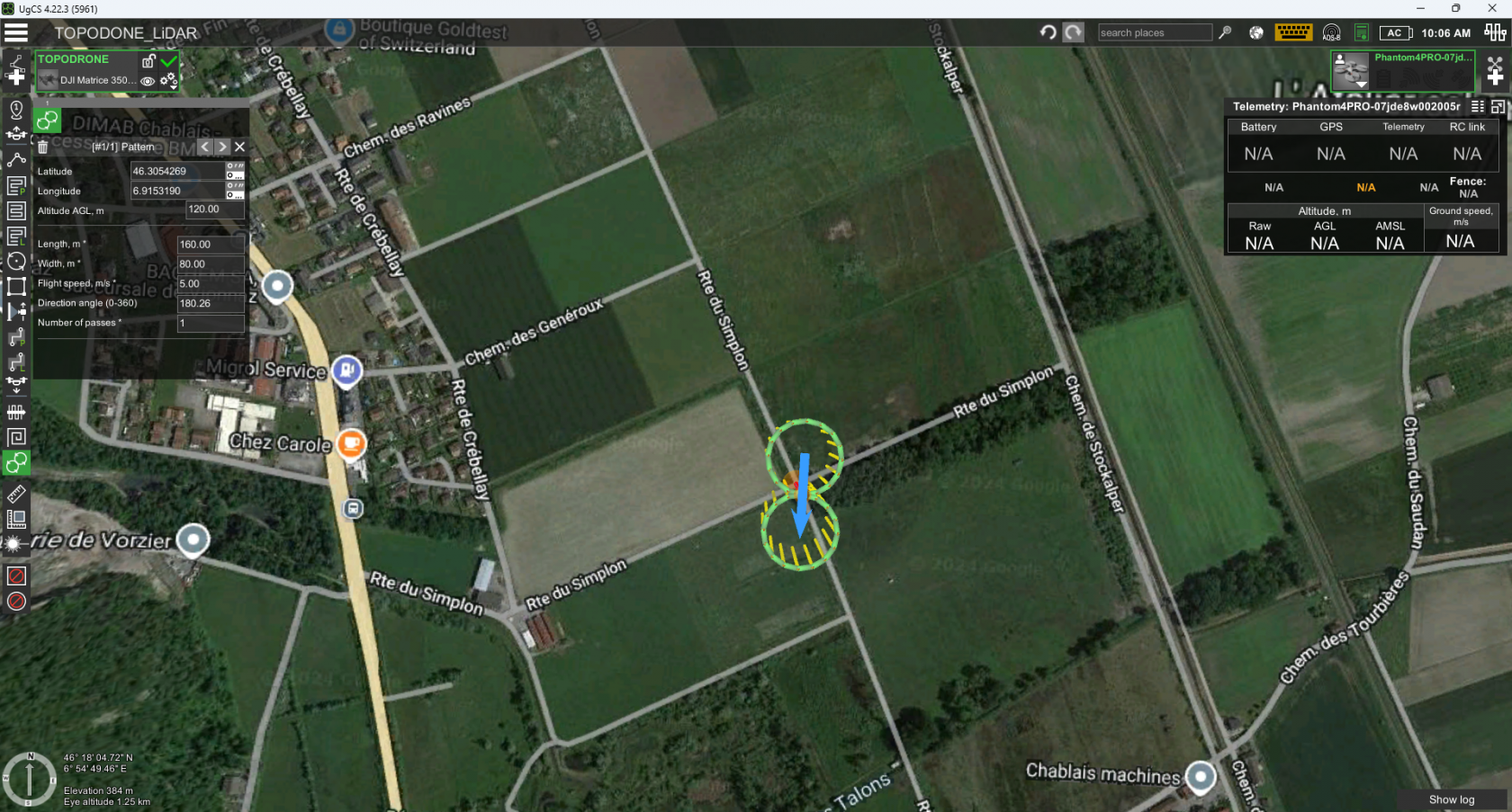
- Set the “Length” and “Width” parameters to 80 and 40 meters respectively

- Set the “Altitude” and “Flight speed” parameters to the altitude and speed of the intended route execution
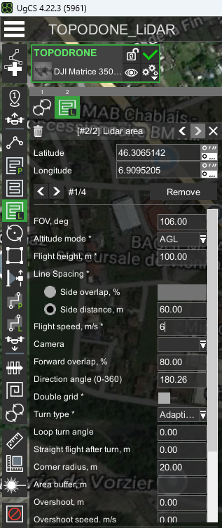
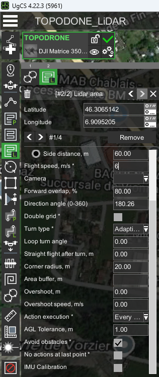
- Using the “Area LiDAR” tool set the area of ALS

- Set the “FOV” parameter to 106 degrees.
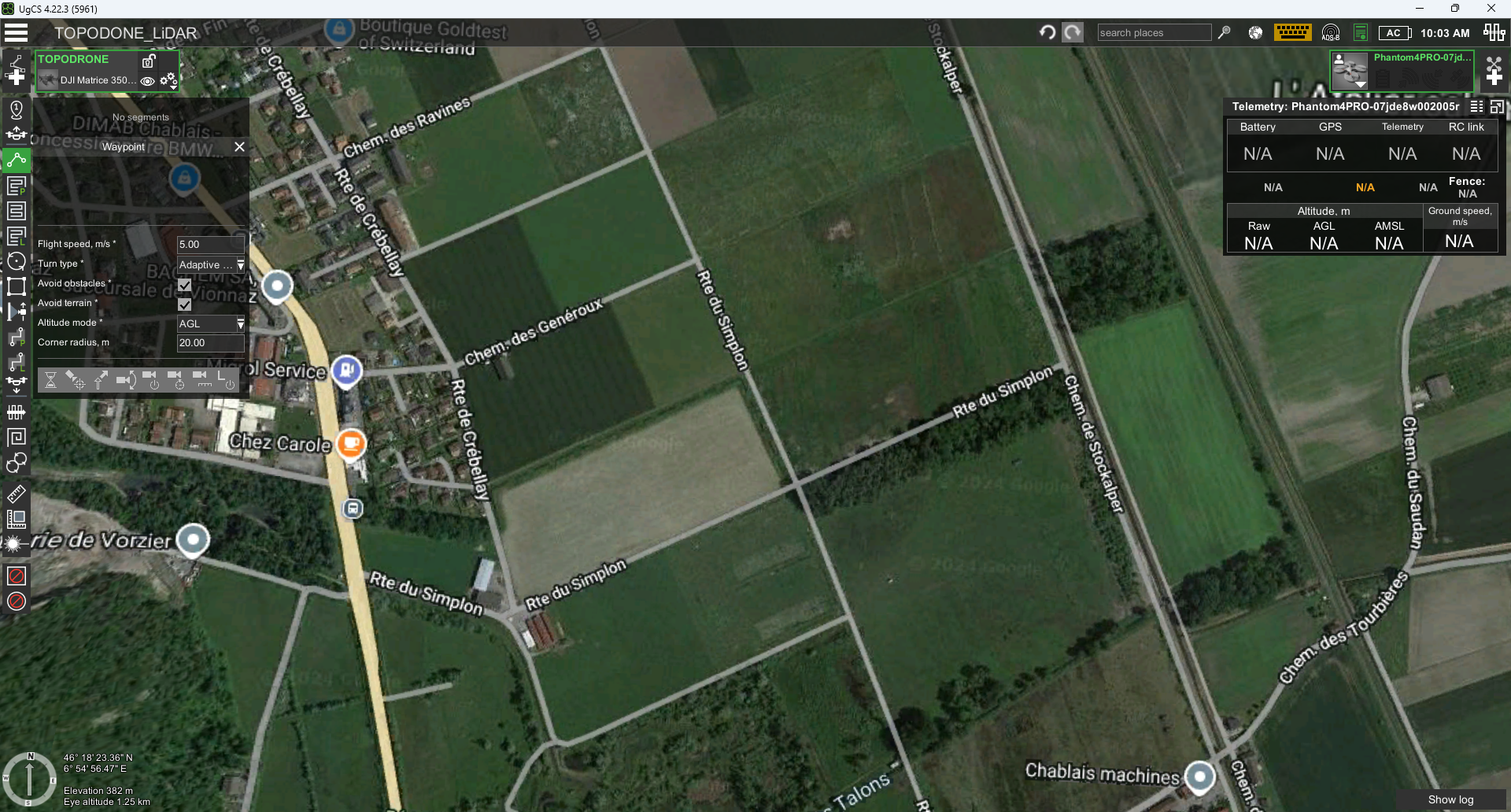
- Set the “Altitude Mode” parameter to AGL or Smart AGL for terrain envelope.
- Set the“Side Overlap, %” to at least 30%, recommended 40-60%.
- Set the “Flight height” parameter to the recommended values for the TOPODRONE LiDAR model.
- Set the “Speed” parameter in the range of 3-12 m/s according to the required performance and point cloud density.
- Set the “Turn type” parameter to Adaptive Bank Turn.
- Uncheck “IMU Calibration” if it is set by default

- Set the “Directional angle” parameter so that the corners are straight.

- Leave the rest of the parameters as default.
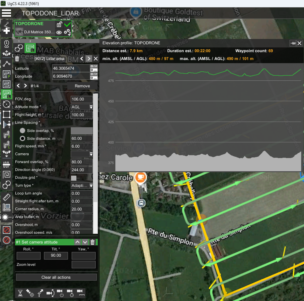
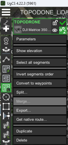
- Click on the “Parameters” button and select “Show elevation” to estimate the flight path relative to the terrain. If necessary, move the vertices of the area slightly. It is convenient to use the value of the direction angle as an integer when there are several routes.
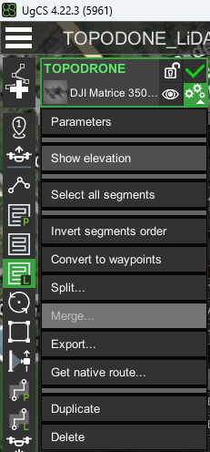

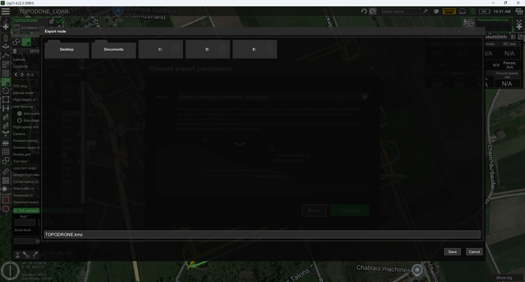
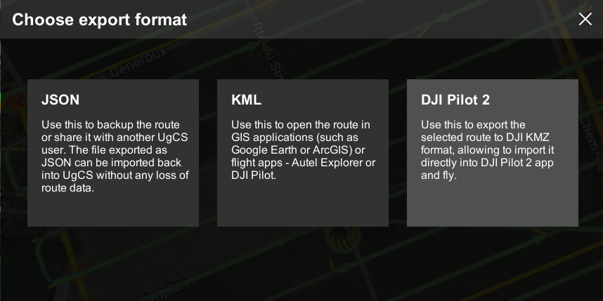
- Click on the “Parameters” button and select “Export...” and select the option “for DJI Pilot 2”.


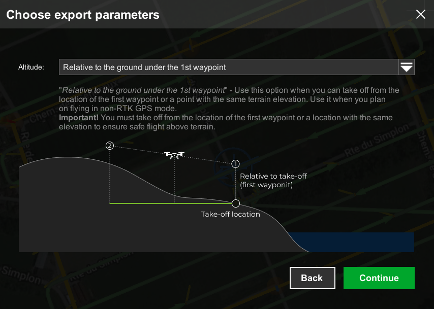
- For “Altitude” select “Relative to the ground under the 1st waypoint” and click “Continue”.
- Save the resulting route to a MicroSD card in *.kmz format
-
Insert the MicroSD card into the DJI M300 RTK or DJI M350 RTK remote control and import the route
The speed and altitude of the drone directly affect the density of the dense laser scanning point cloud.


No Comments